Geology Reference
In-Depth Information
Normal Fault Linkage, Topography, Tilt, Displacement, and Basin Filling
CASE 1
CASE 2A
CASE 2B
CASE 3
Normal fault
Map
View
and
Basin
Geometry
Basin
View from
HW Normal
to Fault
Surface
late
early
Fault overlap
Fault overlap
Intrabasin high
Younger
unit
Hanging
Wall
Tilt
Footwall
Elevation
Proile
Total
Diplace-
ment
HW
Stratal
Thickness
Cross
Section
Younger
unit
Basement
Younger unit
Basement
Younger unit
Basement
Basement
Stranded relay ramp
Older units
Older
units
Younger units
Older units
Younger units
Older units
Younger units
Younger units
Basement
Basement
Basement
Basement
Basement
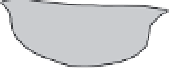
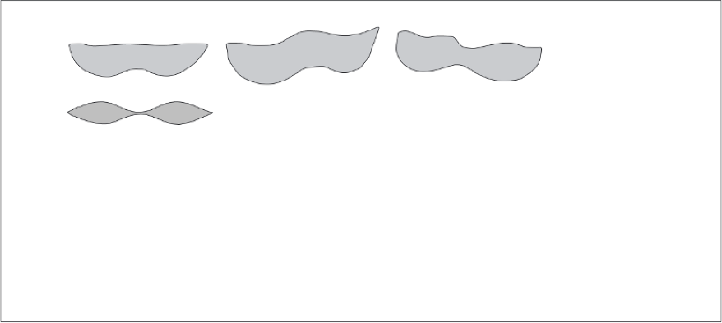
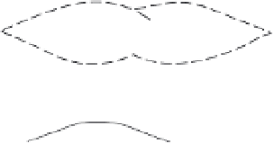
Fig. 10.14
Displacement and basin characteristics for linking or overlapping normal faults.
Four scenarios for linkage geometry and associated structures and basins. In the map view (top row), the shaded area represents the hanging-wall basin with
contours on the sediment thickness. In the view from the hanging wall, the dashed line (cases 2 and 3) represents the predicted geometry following more
displacement. Note that all cases have the same total displacement and displacement gradient, but that differences in stratal tilting and footwall topography
distinguish among them. Case 1: faults link along a plane. Case 2A: rearward fault intersects the frontal, basinward fault. Case 2B: frontal, basinward fault
intersects rearward fault. Case 3: overlapping, but non-intersecting faults. Modified after Anders and Schlische (1994).