Graphics Reference
In-Depth Information
You may also need to change the Direc-
tion option to get a straight extrusion. In
this example, the direction was changed
to “Y Axis.”
When you are satisfied, click Accept the
top navigation bar. Our model now
looks like
Figure 6-32
.
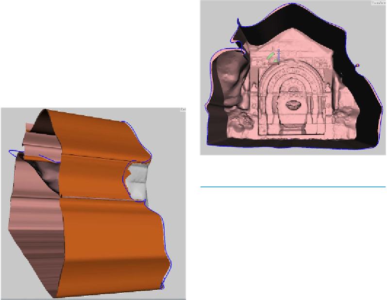
Figure 6-33.
Rotated model
Sometimes MeshMixer will
crash at this stage. It will usu-
ally allow you to open the mod-
el again. Save often in the de-
fault MeshMixer
.mix
format to
ensure that none of your
changes are lost.
Transform faces
From the Deform menu, select Trans-
form Faces.
Arrows in the
x
,
y
,
z
plane will appear.
Scale the extrusion in by dragging on
the white box between the arrows.
Do not close the hole completely.
Figure 6-34
shows this.
Then click Accept.
Figure 6-32.
Extruded sides
Smooth, then rotate
From the top navigation bar, click on
Modify Selection menu and select
Smooth Boundary.
Then click Accept.
Rotate your model so that you are look-
ing head on at the open area. (See
Figure 6-33
.)
Erase and fill
Now we need to close the hole. From the
Edit menu (under Select), select Erase &
Fill.
Then click Accept. The result is shown in
Figure 6-35
.