Graphics Reference
In-Depth Information
I like to disable the fan for the first layer to
keep the plastic as gooey and liquid as pos-
sible, to keep it stuck to the bed (this is es-
pecially popular with PLA printing). You can
also check a box to keep the fan on at all
times, from print start to end.
The cooling thresholds give you more ad-
vanced control over when the fan starts. In
general, layers with shorter print times (such
as the tip of a cone) are more difficult for the
printer to complete successfully, and there-
fore benefit most from additional airflow.
Figure 5-20.
Cooling settings
The thresholds to set for decreased printing
speed will come with time and lots of exper-
imentation, but I think these are a good start-
ing point:
As you adjust the following settings, refer
back to the description under the enable au-
to cooling box to see how your edits will
change the intelligent cooling activity of the
machine during printing.
Enable fan if layer print time is below
60 seconds
Slow down if layer print time is below
15 seconds
Fan speed is a percentage and is really up to
you. Do a few prints with cooling enabled
and increase the minimum fan speed if you
notice that your plastic is drooping or exces-
sively sticking to the nozzle. Bridges fan
speed is how fast the fan will turn during
bridging—keep this high to promote cool-
ing and minimize drooping.
Min print speed
10 mm/sec
You can set the minimum print speed fairly
low; this will result in a great variation in print
speed during more challenging prints.
You may find that separate cooling thresh-
olds are necessary for different parts, so cre-
ating a different slicing profile for each may
be the quickest solution—for example, one
for objects with lots of narrow columns, and
one for hollow objects, one for busts (where
detail is important).
Step 4: Printer Settings
Now we can move onto the Printer Settings
tab (
Figure 5-22
). Before we start with gen-
eral settings, break out the ruler. Measure the
usable length and width of your print area,
and enter the results into the bed size boxes.
The print center should be half of the bed
length and width, so that the print starts at
the exact center of the build platform.
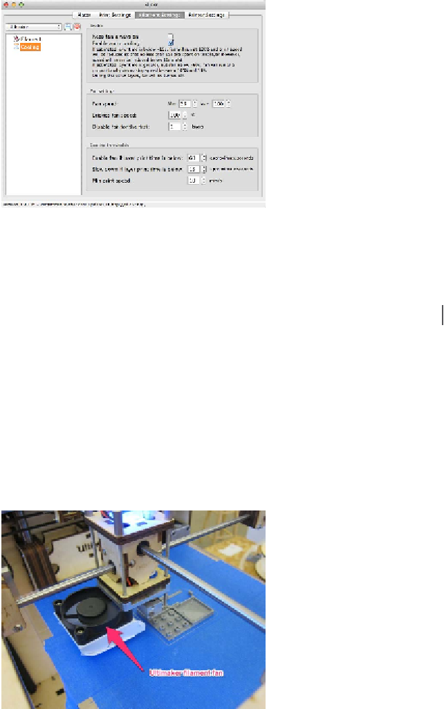
Figure 5-21.
The Ultimaker fan