Biomedical Engineering Reference
In-Depth Information
Working distance
Focal length
Working distance
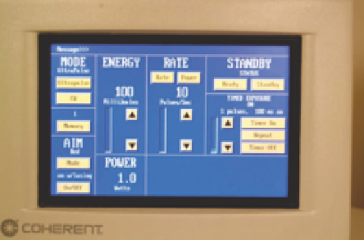
Figure 1.8
Instrument panel of a common carbon dioxide laser. The panel is
intuitive once the operator is experienced.
Focal length
Figure 1.9
A focusing handpiece like that typically used with continuous wave
carbon dioxide laser. Operator can vary spot size and therefore power density
“on the fl y” simply by moving the handpiece away and toward the skin surface.
Most lasers in modern skin surgery are pulsed, and the
“instrument” panel fi elds are given in terms of pulse duration
and fl uence. Also, the spot size is often displayed. However,
some carbon dioxide (CO
2
) lasers, for example, provide only
the pulse energy on the panel, or in CW mode, the number of
watts. Likewise, our photodynamic therapy (PDT) system (a
KTP-pumped 630-nm dye laser) gives the display in “watts.”
In these cases, one must know the spot size and time (in CW
applications) to calculate the total light dose (fl uence). It is
helpful in these cases to attach a sheet of paper on the side of
the laser with different fl uences for the various spots and times.
In CW mode, the user must know the spot size, exposure
time, and power density to determine the fl uence. In many
CW applications (e.g., wart treatment with CO
2
laser), the fl u-
ence is not too helpful in characterizing the overall tissue
effect. One normally observes the tissue responses in real time
and suspends the procedure when an appropriate endpoint is
reached. On the other hand, in PDT applications with CW
light, the total fl uence and power density are very important in
predicting the tissue response.
For CW mode, the CO
2
laser is typically used with a noncol-
limated handpiece. This allows one to control the spot size, as
the operator can vary the power density or fl uence simply by
moving the handpiece tip toward or away from the skin
(Fig. 1.9). For the accomplished laser surgeon, particularly in
ablative applications for small lesions, this confi guration offers
“on-the-fl y” fl exibility and control not available with more
modern locked-in spot sizes and fl uences.
The “enlightened” laser practitioner should have an
intimate
knowledge of his particular devices. For example, some lasers
“know” what spot size is being used (e.g., insertion of the
handpiece into the calibration port can signal the spot size to
the laser), whereas with others, you select the spotsize on the
display, and the laser calculates the fl uence accordingly. For
example, one of our Q-switched lasers has a toggle that allows
us to choose 2-, 4-, or 6-mm spots. However, the handpiece
does not communicate the spot size to the laser control system.
The user “tells” the laser what spot is to be used, and the laser
calculates the fl uence based on this user input. In this case, if
one inadvertently changes the spot size (e.g., by inadvertently
moving the toggle to the 2-mm from the 4-mm spot), the laser
still “thinks” the 4-mm spot is being used, so that the actual
Figure 1.10
Immediate postoperative result on tattoo on shoulder. In this case,
the operator inadvertently moved the toggle “spot size” switch from 4 to
2 mm. Fluence in 532 Q-switched mode increased from 3 to 12 J/cm
2
(fourfold
increase). This resulted in loud snap and punctate bleeding.
surface fl uence is now 4× fl uence on the panel. The resulting
small spot, which impacts the skin with a loud snap and punc-
tate bleeding, should alert the savvy operator that something is
amiss (Fig. 1.10). The operator then can examine the device
and ensure that all the knobs are in the proper position before
proceeding. The reader should note well that if tissue response
looks unusual, most likely there is a problem and the physician
should do a laser “walk around” before proceeding (akin to the
pilot who dutifully checks the exterior of his plane before tak-
ing off). Most newer lasers allow for calibration through the
end of the handpiece. This confi guration allows for interroga-
tion of the entire system, from the lamps to the fi ber to the
handpiece optics. This setup ensures that any problem is iden-
tifi ed before patient care. For example, if a fi ber is damaged,
the laser will be unable to “make” calibration, and a failure
message appears on the panel.
There are some quick and dirty, but not infallible, ways
to check for system integrity. One can examine the aiming
beam as it illuminates a piece of white paper, checking that the
beam edges are sharp (usually the aiming beam and treatment