Graphics Programs Reference
In-Depth Information
3. With the shortcut menu on this tab, choose the
Modify
option in the
Page Setup
manager. In printer/plotter select
DWG to PDF.pc3
; Paper
size,
ISO full bleed A3 (420.00 x 297.00 MM)
; plot style tale,
mono-
chrome.ctb
; and check the option
Display plot styles
. Press
OK
and
Close
.
4. If there is already a viewport, delete it. We create and activate a layer
called
Viewports
, with the
No plot
property.
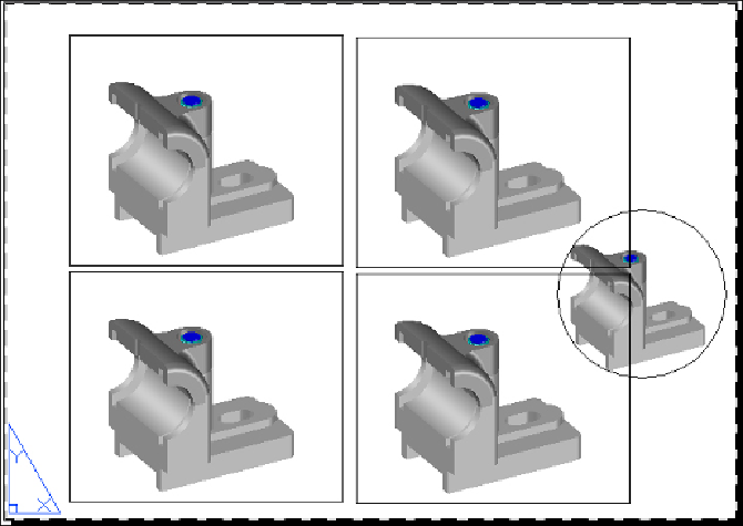
5. With the
MVIEW
command, create one rectangular viewport and copy it
three times. Then, create a circle and, with the
MVIEW
command's
Object
option, define a viewport delimited by the circle:
6. Now, we are going to define what to see inside each viewport. Double-
click inside the top-left one, change the visual style to
2D Wireframe
, and
specify a
Front
view (for instance, with the
ViewCube
tool).
7. Activate the top-right viewport with a single click, change the visual style
to
2D Wireframe
, and specify a
Left
view. To the lower-left viewport, ap-
ply the same visual style and specify a
Top
view. To the lower-right view-
port, again, apply the same visual style, but maintain a perspective view.
Search WWH ::

Custom Search