Civil Engineering Reference
In-Depth Information
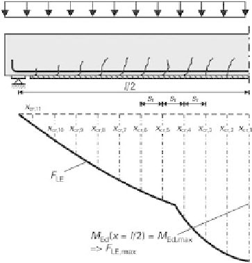
Fig. 4.4
Concrete elements between cracks. (half span, schematic)
According to DAfStb guideline part 1, RV 6.1.1.3.6 (RV 2), the superposition principle
does not apply in this analysis. However, as this example involves a statically
determinate simply supported member, the load combination that produces the maxi-
mum moment is also the most unfavourable combination for checking the bond.
Discrete concrete elements between cracks, starting at the maximum moment, are
arranged according to the schematic drawing of Figure 4.4. First of all, the strip forces at
each crack are determined and then, following calculation of the bond strength, an
analysis is carried out for every concrete element between cracks.
4.5.4.1 Determining the strip forces
As an example, we shall determine the stress resultants at the third crack. From
Figure 4.4 the position of this crack is
4300
2
2
?
200
:
96
1748
:
08 mm
1
:
75 m
The moment at the ultimate limit state after strengthening is required for the calculation
(load case 3):
l
2
2
?
s
r
x
cr
;
3
p
?
x
cr
;
3
2
16
:
95
?
1
:
75
2
2
p
?
l
2
?
x
cr
;
3
16
:
95
?
4
:
3
2
m
Ed
?
1
:
75
37
:
81 kNm
=
m
In addition, we require the moment at this point during strengthening to determine the
prestrain (load case 2):
p
?
x
cr
;
3
2
75
2
p
?
l
2
?
x
cr
;
3
4
?
4
:
3
4
?
1
:
m
E
;
0
?
1
:
75
8
:
92 kNm
=
m
2
2
In a similar way to Section 4.3, using this moment results in a prestrain
ε
s,0
=
0.72 in the
reinforcing steel and
ε
c,0
=
0.20 in the concrete. The strain at the bottom edge of the
cross-section during strengthening is therefore


Search WWH ::

Custom Search