Civil Engineering Reference
In-Depth Information
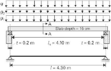
Fig. 4.1
System for strengthening the slab in the example
Loads on the system in kN/m
2
for the various load cases.
Table 4.1
Load case
1
2
3
g
1,k
(dead load)
4.0
4.0
4.0
g
2,k
(
(fitting-out load)
2.0
—
3.0
q
k
(imposed load, category A)
2.0
—
5.0
p
rare
g
1
;
k
g
2
;
k
q
k
4
3
5
12 kN
=
m
2
In order to determine the prestrain condition during strengthening, which according to
DAfStb guideline [1, 2] part 1 section 5.1.1 (RV 19) must be considered for a quasi-
permanent load combination, we get the following for load case 2:
X
X
G
k
;
j
P
1
ψ
2
;
i
?
Q
k
;
i
j
1
i
m
2
p
perm
g
1
;
k
4kN
=
4.1.3
Construction materials
4.1.3.1 Near-surface tensile strength
DAfStb guideline [1, 2] part 1 section 3.1.2 (RV 10) requires the near-surface tensile
strength of the member to be determined. Five values are found by testing, which are
given in Table 4.2.
According to DAfStb guideline [1, 2] part 4 annex A, the value expected for the mean of
the near-surface tensile strength must be determined for the design from the random
sample of
five values:
!
n
?
X
n
1
mm
2
f
ctm
;
surf
f
m
f
i
k
?
s
2
:
28
0
:
953
?
0
:
19
2
:
1N
=
i
1


Search WWH ::

Custom Search