Civil Engineering Reference
In-Depth Information
If the limit according toEquation 3.67 is exceeded, the force for the surface-mounted links
required can be calculated via the ratio of the stiffnesses of the lines of longitudinal
reinforcement:
8
<
EA
L
EA
L
EA
s
?
V
Ed
V
Ed
V
Rds
V
LEd
max
(3.69)
:
3.4.2 Shear strengthening
If the shear strength of the member to be strengthened is inadequate, the shear capacity
in the DAfStb guideline [1, 2] can be increased with the help of shear strengthening.
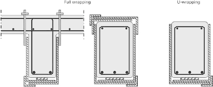
Shear strengthening includes full wrapping and U-wrapping, as shown in Figure 3.10.
Shear strengthening in the form of U-wrapping is only permitted on beams with a
rectangular cross-section, not on T-beams. Although a marginal increase in the shear
strength of T-beams with U-wrapping has been observed in tests, a reliable mechanical
model corresponding to the German level of safety is, however, not available at the
moment owing to the lack of anchorage of the wrapping in the compression zone.
In principle, in the DAfStb guideline [1, 2], increasing the shear strength involves
adding the component from the strengthening to the component from the shear strength
of the unstrengthened member according to DIN EN 1992-1-1 [20] with its associated
National Annex [21]. Both components are based on the truss model of the Eurocode
with variable strut angles. The load-carrying capacity of the tie in the truss can be
calculated in a simpli
ed form in the DAfStb guideline [1, 2] using Equation 3.70.
Besides the load-carrying capacity of the tie, that of the strut, which is not only directly
influenced by the strengthening, must be verified according to DIN EN 1992-1-1 [20]
Equation 6.9 for shear strengthening using the chosen strut angle.
V
Rd
V
Rd
;
s
V
Rd
;
Lw
(3.70)
Fig. 3.10
Potential shear strengthening schemes


Search WWH ::

Custom Search