Civil Engineering Reference
In-Depth Information
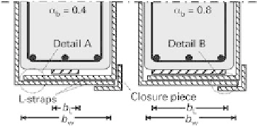
Fig. 3.9
Section through downstand beam with externally bonded CFRP strip and shear wrapping
possible depending on the geometry factor 0.4
α
b
=
b
L
/
b
w
0.8:
0
:
8
α
b
0
α
b
0
:
4
0
:
4
F
u
α
b
F
u
;
2
?
F
u
;
4
?
(3.55)
:
4
The contact pressures depend on the stiffness of the shear wrapping in all cases. It is
therefore necessary to calculate the stiffness of the shear wrapping
first, which
according to the detailing rules of Figure 3.9 is generally made up of two L-straps
and one closure piece bonded with adhesive (see also Section 3.7). Consequently, we
should distinguish between Detail A, consisting of two bonded L-straps, and Detail B,
with two L-straps plus one closure piece (see Figure 3.9). Calculating the increase in the
bond force must include determining the stiffness depending on the cross-sectional
area
A
s
and the moment of inertia
I
s
of steel L-plates for both details. The stiffness for
Detail A
is given by Equations 3.56 and 3.57:
I
S
A
S
?
z
S
;
A
EI
S
;
A
2
?
E
S
?
(3.56)
1
2
?
t
Lw
0
:
5
z
S
;
A
(3.57)
Correspondingly, the stiffness for
Detail B
is given by Equations 3.58 and 3.59:
A
S
?
z
S
;
B
EI
S
;
B
2
?
E
S
?
I
S
E
S
I
S
(3.58)
z
S
;
B
t
Lw
1
(3.59)
Using these variables it is now possible to determine the contact pressures for the two
limit cases
α
b
=
0.4 and 0.8. The contact pressure for
limit case
α
b
=
0.4
can be
calculated using Equations 3.60 to 3.63. This results in the lengths
l
1
=
0.3
b
w
20 and
l
2
=
b
w
40. The crack width for CFRP strips is then
w
=
0.35.
2
?
24
?
EI
s
;
g
;
α
b
0
:
4
3
?
α
4
?
α
26 400
?
EI
s
;
g
;
α
b
0
:
4
11 000
?
l
1
2
:
4
?
EI
s
;
g
;
α
b
0
:
4
F
u
;
2
?
l
2
?
w
1
(3.60)
3
!
EI
s
;
g
;
α
b
0
:
4
4583
?
l
1
w
1
w
1
?
0
:
1
(3.61)
EI
s
;
g
;
α
b
0
:
4


Search WWH ::

Custom Search