Civil Engineering Reference
In-Depth Information
factor
κ
h
=
2000 for planar reinforced concrete members and
κ
h
=
0 for prestressed
concrete members, which likewise take the influence of curvature into account. As the
proposed equation was worked out numerically between certain limits, these may not
be exceeded. One of these limits is the additional ultimate strain for bonded
reinforcement amounting to 10mm/m, which may not be exceeded. It should be
noted that Equation 3.36 has various units and all values must therefore be entered in
N and mm.
p
s
r
κ
h
098
?
s
4
=
3
h
?
s
1
=
3
τ
L1k
?
2
:
3
?
τ
LFk
?
0
:
r
r
Δ
F
LRd
?
b
L
(3.36)
γ
BA
3.3.4
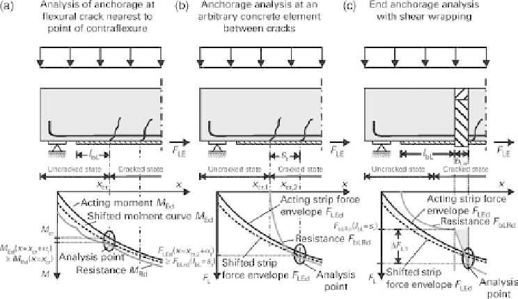
End anchorage analysis
3.3.4.1 General
As was already explained in Section 3.3.3.1, an analysis of the end anchorage is
necessary in addition to checking the bond at the element between cracks. According to
the DAfStb guideline [1, 2], the end anchorage analysis can be performed in three
different ways (see Figure 3.8) depending on requirements.
3.3.4.2 End anchorage analysis at
flexural crack nearest to point of contra
exure
The analysis at the
flexural crack closest to the point of contra
exure represents the
standard case (Figure 3.8a). In this case the moment acting at this
flexural crack must
be lower than the resistance of the cross-section taking into account the 'shift rule'
according to DIN EN 1992-1-1. The resistance of the cross-section is determined based
Fig. 3.8
Scheme for analysing the three different options for verifying the end anchorage of
externally bonded CFRP strips and CF sheets


Search WWH ::

Custom Search