Civil Engineering Reference
In-Depth Information
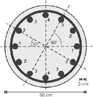
Fig. 8.3
Scheme for determining
z
j
s
and
A
j
s
φϕ
sw
ϕ
s
25
2
r
s
D
=
2
c
2
250
30
10
197
:
5mm
Consequently, we get the following figures for the bars marked with number 1:
2
?
π
981
:
7mm
2
25
2
A
s
;
1
2
?
z
s
;
1
sin
0
°
?
r
s
0
We proceed similarly for the bars marked with numbers 2, 3 and 4:
2
?
π
25
2
5mm
2
A
s
;
2
4
?
1963
:
z
s
;
2
sin
30
°
?
r
s
0
:
5
?
197
:
5
98
:
8mm
2
?
π
25
2
5mm
2
A
s
;
3
4
?
1963
:
z
s
;
3
sin
60
°
?
r
s
0
:
866
?
197
:
5
171
:
0mm
2
?
π
25
2
7mm
2
A
s
;
4
2
?
981
:
z
s
;
4
sin
90
°
?
r
s
197
:
5mm
It is now possible to calculate the idealized second moment of area of the column cross-
section:
0
?
10
6
8
2
0
2
5
2
I
i
3068
:
6
:
1
1
?
98
:
?
1963
:
5
171
:
?
1963
:
5
197
:
?
981
:
7
3653
:
9
?
10
6
mm
4
8.4
Boundary conditions
Prior to calculating the load-carrying capacity of the column, it is
rst necessary to
check whether the column may be strengthened using the method given in the guideline.

Search WWH ::

Custom Search