Civil Engineering Reference
In-Depth Information
ξ
2
factor to allow for the geometry of the compression member and the strain in the
confining reinforcement according to Equation 7.23.
f
cc
f
c
α
1
1
:
17
0
:
2
?
(7.21)
N
bal
N
u
0
:
8
?
f
cc
?
A
N
u
ξ
1
1
(7.22)
l
0
D
1
ξ
2
1
:
15
0
:
06
?
ρ
ε
0
:
01
0
:
012
?
ρ
ε
?
(7.23)
ρ
ε
ε
ju
ε
c2
(7.24)
where:
f
c
compressive strength of concrete subjected to uniaxial loading
ρ
ε
strain coef
cient.
In order to determine the theoretically admissible axial load
N
u
, the relative angle
θ
must
be calculated iteratively within the permissible range of answers by equating the two
expressions (7.19) and (7.20) solved for
N
u
.
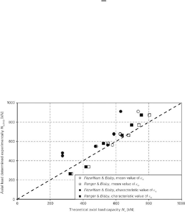
Figure 7.7 compares the theoretical load-carrying capacity calculated using the modified
expressions (7.19) and (7.20) of
Jiang
with the results of the experimental studies of
Fitzwilliam
and
Bisby
[136] as well as
Ranger
and
Bisby
[137]. In their tests on
Fig. 7.7
Comparison of the modi
ed approach of Jiang for member loadbearing capacity with the
results of the experimental studies by
Fitzwilliam
and
Bisby
[136] and
Ranger
and
Bisby
[137]


Search WWH ::

Custom Search