Civil Engineering Reference
In-Depth Information
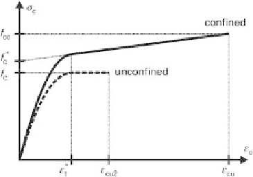
Fig. 7.6
Simpli
ed stress
-
strain curve for design
8
<
2
E
c
E
2
2
c
E
c
?
ε
c
?
ε
for 0
ε
c
ε
t
4
?
f
c
σ
c
(7.9)
:
f
c
E
2
?
ε
c
for
ε
t
ε
c
ε
cu
where:
E
2
slope of straight line according to Equation 7.10
E
c
tangent modulus of uncon
ned concrete subjected to uniaxial compression
f
c
*
point at which projected straight part of curve intersects stress axis according to
Equation 7.11
σ
c
compressive stress in confined concrete
ε
c
longitudinal compressive strain in confined concrete
ε
cu
longitudinal strain in confined concrete at failure of fibre-reinforced material
according to Equation 7.12.
f
cc
f
c
ε
cu
E
2
(7.10)
0
@
1
A
s
w
2
2
D
c
?
f
c
f
c
k
?
ρ
wy
?
f
wy
Δ
p
(7.11)
D
E
jl
?
ε
ju
f
cm
ε
cu
ε
c2
?
1
:
75
19
?
(7.12)
where:
D
diameter of reinforced concrete column
D
c
diameter of core area of column confined by reinforcing steel
E
jl
relative stiffness of confining reinforcement made from CF sheet
f
cc
admissible compressive stress in confined concrete at failure of fibre-reinforced
material according to Equation 7.13
f
wy
yield strength of confining reinforcing steel


Search WWH ::

Custom Search