Civil Engineering Reference
In-Depth Information
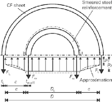
Fig. 7.4
Transverse compression stresses in a con
ned compression member
2
?
F
L
D
2
?
t
L
?
E
L
?
ε
ju
D
p
1
(7.4)
p
1
?
c
2
?
t
L
?
E
L
?
ε
ju
t
w
;
eff
?
f
wy
2
?
F
L
F
w
p
1
?
c
p
2
(7.5)
D
c
c
D
c
c
where:
t
L
theoretical thickness of
fibre cross-section in CF sheet
E
L
modulus of elasticity of surface-mounted CF sheet relative to
fibre cross-section
ε
ju
ultimate strain in
fibre-reinforced material around member
t
w,eff
thickness of distributed con
ning reinforcing steel
f
wy
yield strength of con
ning reinforcing steel
c
concrete cover
D
diameter of reinforced concrete column
D
c
diameter of core area of column con
ned by reinforcing steel.
The decrease in transverse compression
Δ
p
can be determined by considering a section
I-I along the distributed reinforcing steel. The following applies:
Z
π
D
c
2
?
sin
2
?
t
L
?
E
L
?
ε
ju
p
1
p
2
?
c
p
1
Δ
p
?
φ
?
d
φ
(7.6)
0
2
?
t
L
?
E
L
?
ε
ju
p
1
p
2
?
c
Δ
p
p
1
(7.7)
D
c
Concrete members in compression strengthened with fibre-reinforced materials exhibit
varying behaviour depending on the intensity of the confining effect. The fundamental
stress
strain curves shown in Figure 7.5 have been observed in experimental studies.
Curve (0) describes the behaviour of an unconfined concrete compression member
subjected to a uniaxial load in a short-term test with deformation control. Curve (1), for
con
ned concrete, exhibits an only marginal increase in the maximum load. In a test
-


Search WWH ::

Custom Search