Civil Engineering Reference
In-Depth Information
by weld toe cracking (to preclude cracking in the weld throat). Many design engineers
also specify CJP flange-to-web welds for open DPG spans to ensure that vertically
applied wheel loads can be safely resisted by the top flange-to-web weld.
7.2.6.1.4.1 Top Flange-to-Web Connection (Simply Supported Girder
Spans)
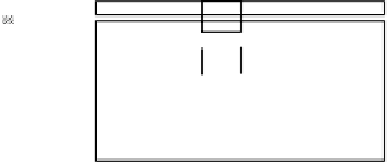
In addition to vertical wheel loads, the top flange-to-web weld connec-
tion must transmit horizontal shear due to the varying flange bending moment, d
M
,
along the girder length.The change in flange force, d
P
f
, due to bending along a length
of girder, d
x
,
(Figure 7.14)
is
d
M
I
¯
(V
d
x)
I
¯
VQ
f
I
d
P
f
=
y(A
f
)
=
y(A
f
)
=
d
x
.
(7.65)
The horizontal shear flow,
q
f
=
d
P
f
/
d
x
, for which the top (compression) flange weld
is designed, is
d
P
f
d
x
=
VQ
f
I
q
f
=
,
(7.66)
¯
where
V
is the shear force,
y
is the distance from the top flange centroid to the neutral
axis, and
Q
f
=
A
f
¯
y
(statical moment of the top flange area about the neutral axis).
The shear force from wheel live load,
W
, with 80% impact (AREMA, 2008), acting
in a vertical direction along the top flange-to-web connection of DPG spans is
1.80
(W)
S
w
w
=
,
(7.67)
where
S
w
is the wheel load longitudinal distribution (
S
w
=
3 ft for open deck girders
or
S
w
=
5 ft for ballasted deck girders).
The resultant force per unit length of the weld is
q
f
w
2
.
q
=
+
(7.68)
The required effective area of the weld can then be established based on the allowable
weld stresses recommended by AREMA (2008) as shown in
Table 7.2
(see also
Chapter 9).
w
P
(
x
+d
x
)
w
P
(
x
)
Flange
__
y
q
Weld
d
x
d
f
h
d
P
f
=
P
(
x
+d
x
)
-
P
(
x
)
Neutral
axis
q
= d
P
f
/d
x
web
FIGURE 7.14
Forces transferred between the flange and web.