Civil Engineering Reference
In-Depth Information
d
A
F
A
y'
M
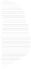
FIGURE 7.5
Shear flow in a beam.
and the shear stress is
d
F
/d
x
t
VQ
I
x
t
,
τ =
=
(7.31)
Ay
is the
where
t
is the thickness of steel at the area,
A
, under consideration;
Q
=
statical moment of area,
A
, about the neutral axis.
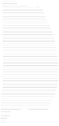
Equation 7.31 results in a shear stress profile through the girder as shown in
Figure 7.6.AREMA (2008) recommends the determination of the average shear stress
computed based on the area of the beam or girder web (
t
avg
=
V/A
w
, where
A
w
is the
area of the web) to simplify steel beam and girder I-cross section design.As shown in
Figure 7.6, this is an accurate (although slightly nonconservative) approach to shear
design.
The AREMA (2008) allowable
s
tress design uses an allowable shear stress based
on tensile yield stress (
F
y
/
√
3, see Chapter 2). The required gross web area of
τ
y
=
Shear flow,
q
Shear stress,
τ
Neutral axis
t
avg
FIGURE 7.6
Shear stresses in an I-beam.