Civil Engineering Reference
In-Depth Information
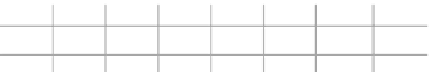
U1
U2
U3
U4
U3'
20'
27.25'
8 @ 19.55' = 156.38'
L0
L1
L2
L3
L4
L3'
20'
FIGURE E5.10
Cooper's E90 nosing load (lateral equipment load) at the bottom lateral
bracing panels
22.5 kips at any panel.
Bracing forces required to resist top chord buckling are shown in Table E5.2:
=
90
/
4
=
Top lateral bracing
:
Due to their slenderness, top lateral bracing compressive members are
assumed to be inactive and tension members only resist the panel forces.
The top lateral bracing member forces are shown in
Table E5.3.
Bottom lateral bracing
:
Since the bracing members are connected to the floor system, both are
assumedtoequallyparticipateinresistingpanelshearforces.Therefore,each
member is required to resist 50% of the panel shear force in both tension
TABLE E5.2
Total Axial
Bracing Force (kips)
Panel
Compression in
(2.5% of Main Member
Point
Top Chord (kips)
Compressive Force)
U1
370
9.3
U2
640
16.0
U3
800
20.0
U4
850
21.3