Civil Engineering Reference
In-Depth Information
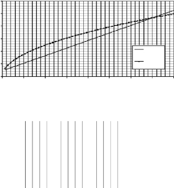
Longitudinal force
600
500
400
300
Braking
force (kips)
Traction
force (kips)
200
100
0
0
50
100
150
200
Length (ft)
250
300
350
400
FIGURE 4.12
AREMA design longitudinal forces.
0.75
0.5
0.25
0
0
50
100
Loaded length (ft)
150
200
HB/LF (Traction)
HB/LF (Braking)
FIGURE 4.13
Bearing forces from European testing. (After Fryba, L., 1996,
Dynamics of
Railway Bridges
, Thomas Telford, London, UK.)
longitudinal forces for the design of span bracing, bearings, substructures, and foun-
dations needs careful consideration. The distribution and path of longitudinal forces
between their point of application and the bridge supports depend on the arrangement,
orientation, and relative stiffness of
• Bridge members in the load path
• Bearing type (fixed or expansion)
• Substructure characteristics.
Example 4.8
The longitudinal design force for Cooper's E80 loading is required for each
track of the open deck steel multibeam railway bridge shown in
Figures E4.1