Hardware Reference
In-Depth Information
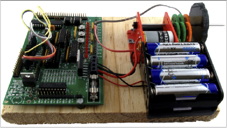
Figure 13-9:
Using the
Gertboard
motor controller
For project building, the Gertboard ofers signiicantly more functionality than a bare
Raspberry Pi. he 12 bufered IO ports, located at the top of the board, can be conigured as
inputs or outputs and provide more connectivity than the seven or eight general-purpose IO
pins provided on the Pi's own GPIO port. he inclusion of LEDs, which indicate when a pin is
high or low, helps with both circuit troubleshooting and electronics education, making it
easy to see what the various inputs and outputs are doing at any given time.
For sensing or feedback projects, the Gertboard's ADC and DAC components are handy addi-
tions. Unlike the GPIO pins on the Pi itself, which can only receive and send digital signals, the
Gertboard includes two ADC and two DAC connections. he ADC pins, located on the upper-
left of the Gertboard, allow analogue components to be converted into digital signals compati-
ble with the Pi. As an example, Figure 13-10 shows how you can use the ADC pins to read the
status of a
potentiometer
—a component which varies its resistance according to the position of
a slider or knob. his circuit could be used to control the Pi's volume in a media centre applica-
tion, or to alter the speed of an attached motor. he DAC pins provide the opposite functional-
ity, taking a digital signal from the Pi and converting it to analogue. his could drive a speaker
to create audio, or alter the speed of a motor or the brightness of an LED.
For more complex projects, the Gertboard provides an open collector driver, which uses tran-
sistors to switch on and of devices that have diferent power requirements to the 3.3 V used by
the Gertboard or that draw a large amount of current and require an external power supply to