Hardware Reference
In-Depth Information
2
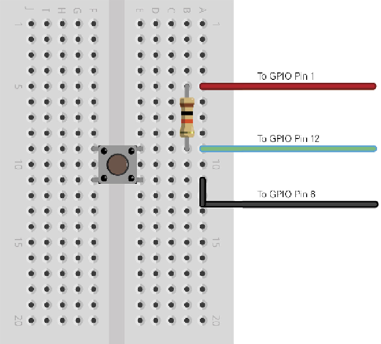
Connect a 10 KΩ resistor to the same row as one of the push-button's legs and an
unused row. his is a pull-up resistor, and will provide the Pi with a reference voltage
so it knows when the button has been pressed.
3
Connect the unused leg of the pull-up resistor to Pin 1 of the Raspberry Pi's GPIO port.
his provides the 3.3 V reference voltage.
4
Connect the unused leg of the push-button switch to Pin 6 of the Raspberry Pi's GPIO
port. his provides the ground connection.
5
Finally, connect Pin 12 of the Raspberry Pi's GPIO port to the other leg of the push-
button switch in the same row as the 10 KΩ resistor. Your breadboard should now
look like Figure 12-5.
Figure 12-5:
he example
breadboard
layout for a
simple push-
button input