Hardware Reference
In-Depth Information
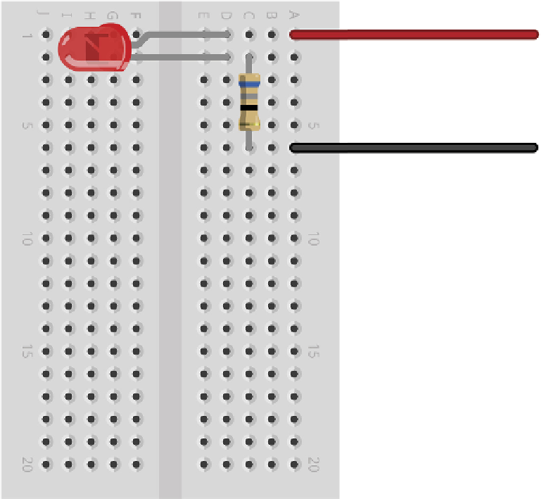
Figure 12-3:
A breadboard
circuit for a
simple LED
output
To GPIO Pin 11
To GPIO Pin11
To GPIO Pin 6
To GPIO Pin 6
At this point, nothing will happen. hat's perfectly normal: by default, the Raspberry Pi's
GPIO pins are switched of. If you want to check your circuit immediately, move the wire
from Pin 11 to Pin 1 to make the LED light up. Be careful not to connect it to Pin 2, though:
a current-limiting resistor suitable for a 3.3 V power supply will be inadequate to protect the
LED when connected to 5 V. Remember to move the wire back to Pin 11 before continuing.
To make the LED do something useful, start a new Python project. As with the projects in
Chapter 11, “An Introduction to Python”, you can use a plain text editor or the IDLE soft-
ware included in the recommended Debian distribution for this project as well.