Information Technology Reference
In-Depth Information
Step 3.
Two points
p2
and
p3
are found such that the distance between the lines with
slope (-1/
m
) passing through
p2
and
p3
is maximum. These points can be easily de-
termined by the method used to find
p1
. After finding
p1
,
p2
, and
p3
, the bounding
rectangle is determined by calculating the four corner points
q1
,
q2
,
q3
, and
q4
.
Step 4.
Step 2 and Step 3 are repeated for each edge (line segment) of the convex
polygon, and the bounding rectangle that has the minimum area is selected. For the
object in Fig. 5 (a), the bounding rectangle corresponding to the hull edge
AB
happens
to be the minimum bounding rectangle which is shown in Fig. 5 (d).
(a) (b) (c) (d)
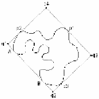
Fig. 5.
Illustration of the minimum bounding rectangle algorithm: (a) A concave object and its
convex hull with four hull edges
AB
,
CD
,
EF
, and
GH
, (b) The convex polygon of the object in
(a) constructed using four hull edges, (c) The bounding rectangle formed using the hull edge
AB
, and (d) The resulting minimum bounding rectangle
4 Method for Identifying the Types of Aurora
In order to build a content-based image retrieval system for aurora images, one must
identify the list of features which can be extracted from the hierarchical representation
and are able to classify images into the desired categories. The extent of the aurora
oval along the two coordinate axes, the orientation of the oval, the presence or ab-
sence of the transpolar arc, the orientation of the transpolar arc, the circularity meas-
ure, the percent of the oval that is visible, the maximum thickness of the oval, and the
location of the aurora itself have been selected. These features appear to be adequate
for identifying
Type1,
Type2
, and
Type3
aurora images. Section 4.1, 4.2, and 4.3
discuss the determination processes of
Type1
aurora,
Type2
aurora, and
Type3
aurora,
respectively. It is shown that all the above features can be computed from the hierar-
chical representation.
4.1 Determination of
Type1
Aurora
A
Type1
aurora is characterized by the transpolar arc as shown in Fig. 6 (a). The edge
image which is used to create the hierarchical representation is also shown in Fig. 6
(a). The hierarchical representation consists of two graph nodes that are not con-
nected to each other. If a transpolar arc is present, then the inner closed curve will
have at least one deep concavity. The location and depth of concavities, if present,
can be determined from the hierarchical representation using the method described in
Section 3.


Search WWH ::

Custom Search