Information Technology Reference
In-Depth Information
μ
1
μ
2
Figure
2.4.
The double-barrier structure of an RTD. The gray areas on the sides
represent metal contacts or reservoirs of electrons with chemical potentials m
1
and m
2
. The horizontal axis is location and vertical axis is energy of the electron.
Thus, as the applied bias is increased, every time a new energy level enters the
range between the two side chemical potentials, there will be a peak in the device's
current versus voltage curve (Fig. 2.6).
If a ''gate'' electrode is placed below the device to enable us to move the
energy levels up and down, then we can use this gate to control which level lies
between the side chemical potentials, and therefore we can control the conduc-
tance of the device. This is the basis of a three-terminal switching device or
resonant tunneling transistor.
Note that the conductance through this device cannot be modeled by simply
considering two single barriers in series. In fact, what is essential here is the wave
nature of the electrons and the resonance phenomenon in the well that leads to a
high transmission probability of electrons from one side to the other, giving rise to
the peaks in conductance. This is analogous to the transmission of light through a
multilayer structure with layer thicknesses on the order of the wavelength of the
incident light or smaller. Resonance phenomena there can lead to high transmis-
sion for a given set of layer properties (thicknesses and refractive indices) and
incident wavelength. In general, this is the problem of a resonant cavity, which in
the case of the RTD is a cavity for electrons.
μ
1
μ
2
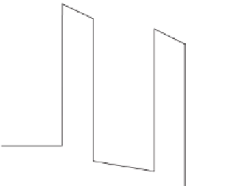
Figure
2.5.
A double-barrier under applied bias, which creates a difference
between the chemical potentials on the two sides.


Search WWH ::

Custom Search