Information Technology Reference
In-Depth Information
A
A
A
1
2
*
*
*
1
A
A
A
A
A
A
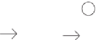
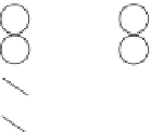
Figure
14.8.
Counting disabled nodes using spin wave.
B. Indexing representative nodes. Now, we must find the appropriate location to
place each representative node in its right graph column. In other words, we must
find each representative node's row index in the graph column. We begin by telling
all the representative nodes (disregarding its type) within a column to communicate
with each other, through a common frequency (i.e., Frequency Active). Now we
find the first or uppermost representative node of any type in a column in constant
time by using a method similar to the Node Elimination procedure. Then we turn
on all switches in the channel and have each representative node send a signal with
an amplitude equal to two (in order to leave two extra slots in the graph column for
itself and its own right neighbor) plus the number of disabled nodes of that type
(obtained from the previous step), and immediately turn off the switch above it to
direct its generated wave downwards. Note that for synchronization purposes, each
representative node generates its spin wave signal after a short time to compensate
the spin-wave propagation delay in the ferromagnetic channel. The time period
should be equal or greater than the distance between adjacent nodes over speed of
spin waves, which is in the order of 10
9
/10
4
=10
13
.Consideringthefactthatthe
frequency is in the order of GHz or even THz, this whole process takes the same
amount of time (constant time) as it would for one signal to travel the entire bus.
Lastly, the amplitude of the superposed wave received by each representative node
will be its row index in the graph column. We illustrate this using the third column
of our example. The first representative node, A, sends a signal of amplitude 4
which is 2 (one for itself and one for its own right neighbor)+2 (the number of
disabled A nodes in that column). The next representative node,
*
, sends 2+0=2
amplitude, which will be superposed with the first signal, making the total signal
have an amplitude of 6. Since the A representative node did not receive any signals,
its row index in the graph column will be 0 whereas the
*
representative node
received a signal with an amplitude of 4 and thus that will be its row index in the
graph column (Figure 14.9).
A
A
4
*
*
A
A
6
A
A
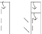
Figure
14.9.
Calculating row indices in graph column using spin wave.


Search WWH ::

Custom Search