Information Technology Reference
In-Depth Information
Inputs
Outputs
Shift register
control
...
...
y
n
−
1
y
i
y
0
p
k
−
1
p
k
−
2
p
0
x
n+p
−
1
x
n
x
n
−
1
x
i
x
0
x
−
1
x
−
p
...
...
...
...
...
1
Shift right
Shift left
P
f
i+d
f
i
−
d
Digital to analog
converter
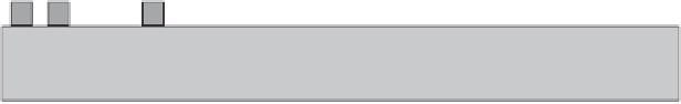
Figure
9.12.
Structure of a nanoscale spin-wave p-shifter with overlapping input/
output nodes.
input with value 1, the priority encoder may have several 1-valued inputs. The
output represents the index of the highest priority input having the value 1. The
priority is a fixed ordering implemented by the encoder; usually, x
N
1
has
the highest priority, whereas x
0
has the lowest [1].
The general way to implement a priority encoder is to have a module called
''priority resolution'' which keeps the highest priority 1 and sets all the other
inputs to 0. These data will be the input to a standard binary encoder which gives
the index of the only input with value 1. In implementing the spin-wave priority
encoder, however, we do not use a ''priority resolution'' module to reset the lower
priority 1-valued inputs to 0. Instead, we use spin-wave switches to force the waves
in the desired direction and arrange the nodes in a fashion that the output node
receives the index of the highest priority 1-valued input.
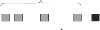
The structure of a spin-wave priority encoder is shown in Figure 9.13. In this
design, the highest priority node, x
N
1
, is placed closest to the output node, while
the lowest priority node, x
0
, the farthest. Note that in the structure shown in
y
k
−
1
y
0
...
Binary outputs:
N =
2
K
Input
A/D
x
0
y
0
Analog
out
x
0
x
1
x
i
x
N
−
1
...
...
y
i
x
i
i
y
k
−
1
x
N
−
1
Spin-wave switch
Spin-wave bus
Figure
9.13.
Structure of a nanoscale spin-wave priority encoder.


Search WWH ::

Custom Search