Information Technology Reference
In-Depth Information
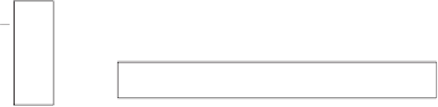
Inputs
Output
x
0
x
k
−
1
x
k
−
2
x
1
x
0
Y
···
x
i
Y
2
K
−
1
2
K
−
2
2
1
f
adc
x
k
−
1
Figure
9.1.
Structure of a nanoscale spin-wave digital to analog converter.
To implement an N-bit digital to analog converter (D/A), we use N nodes as
inputs and one node as the output, all connected to the spin-wave bus. Assuming
that the output is the rightmost node, the N-bit digital value gets mapped to
the N input nodes such that the most significant bit (MSB) is mapped to the
leftmost node, and the least significant node (LSB) to the rightmost node. The
index of these nodes starts at zero for the rightmost node and continues to N
1
for the leftmost node. A fixed value equal to 2
index
is assigned to each of these
nodes.
To compute the analog value, each node checks its input value; if equal to
''1,'' it sends a spin wave on the bus with an amplitude equal to its assigned fixed
value. Note that all the senders' frequencies are the same as the frequency at which
the output is tuned. The output node receives the superposition of all the waves,
which is equal to the analog value represented by the N input bits. Figure 9.1
illustrates the structure of a spin-wave digital to analog converter.
The digital to analog converter module has several applications. For instance,
it is used in the design of decoders, multiplexers, and demultiplexers as shown in
the next sections.
9.2.2. Nanoscale Spin-Wave Full Adder
A k-input full adder is a device that adds the two k-bit input values and a carry-in
value and generates a k-bit sum and a 1-bit carry-out [1]. The structure of a spin-
wave k-bit full adder is shown in Figure 9.2. It consists of k nodes representing
input x, k nodes representing input y, one node for c
in
, and one node for analog
value of the output, z. These nodes intercommunicate via the spin-wave bus.
All the input nodes' sending frequency is tuned on the receiving frequency of
the z. The inputs x and y are converted to analog value using two digital to analog
converters (D/A). The c
in
node broadcasts its value on the spin-wave bus at
the same time as all the other input nodes broadcast 2
i
x
i
and 2
i
y
i
, for i=0
k
1, explained in Section 9.2. All these waves get superposed and the output
node z receives the analog value of this summation. Similar to a spin-wave
encoder, the internal A/D converts this value to k+1 bit binary value. The most
significant bit (MSB) of this binary value is the c
out
, while the rest of the bits
represent the sum value.


Search WWH ::

Custom Search