Information Technology Reference
In-Depth Information
biased by a negative voltage. There is a self-alignment mechanism that makes the
proposed structure tolerant to structure imperfections.
The detailed analysis of the spin wave switch can be done on the base of the
Heisenberg model, treating the ferromagnetic film and the DMS cell as two media
having different exchange integrals J. The Hamiltonian for the system ferromag-
netic film plus DMS cell can be expressed as follows:
H
¼
X
i
;
j
J
ij
½
S
i
S
j
;
where J is the exchange integral for the nearest spins in the lattice. The
propagation/reflection of spin waves through the interface between the DMS
cell and the ferromagnetic film depends on the ratio J
DMS
/J
film
, where J
DMS
and
J
film
are the exchange integrals for the DMS cell and the ferromagnetic film,
respectively. The exchange integral in the ferromagnetic film is constant, while the
exchange integral in the DMS cell is a function of the gate voltage J
DMS
J
DMS
(V
G
). In the two ultimate limits J
DMS
/J
film
=1 and J
DMS
/J
film
=0,wehave
complete transmission and complete reflection, respectively.
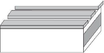
The same structure of the spin-wave switch based on the effect of hole-
mediated ferromagnetism may be used for the vertical integration of the spin-wave
buses. In Figure 7.4 we have schematically shown two vertically separated
ferromagnetic films with a spin-wave switch in between. The switch serves as a
connector between two spin-wave busses in this structure.
At the negative applied bias (ferromagnetic phase), the switch allows spin
wave propagate from one film to another. At the positive bias (paramagnetic film),
spin waves can not propagate through. The use of the spin-wave switches for
vertical integration makes possible array-based architectures similar to the one
proposed for the array of nanowires [11]. The advantage of the proposed
architecture is that signal information can be encoded in the phase of the
propagating spin wave rather than in the number of electrons to be transmitted
via conducting wires.
Feromagnetic
buses
V
G
Switch
Figure
7.4.
Spin-wave crossbar with spin-wave switches.


Search WWH ::

Custom Search