Information Technology Reference
In-Depth Information
the recording head is centered with respect to an island of the patterned SUL. In
the second case, the recording head is centered with respect to a groove between
two adjacent islands. In other words, in the second case, the head is a half-period
offset with respect to an island. The respective field profiles along same line, 5 nm
away from the surface of SUL, along a patterned direction are shown in Figure
6.11b. The fact that the field profiles are so different from each other clearly
indicates the above mentioned process of ''patterning'' the recording field. One
can observe the field in the centered case is larger (by more than a factor of two)
and substantially more localized compared to the field in the off-centered case.
This means that the head itself is going to substantially improve its recording
quality when it is recording information in the favorite positions (compared to any
off-centered positions). This is in contrast to the conventional recording process in
which the recording field profile does not depend on the location of the head with
respect to the media, regardless of whether the media being patterned or not.
Improved Localization of Recording and Sensitivity Field across the Thick-
ness: Furthermore, the effective field patterning, as described above, takes place
across the entire thickness of the recording media. In other words, the recording
and sensitivity fields could be strongly localized not only at the air bearing surface
of the head but also across the entire thickness of the recording layer. Figure 6.11c
and d illustrate the recording field profiles for the two cases of a recording system
with a patterned soft underlayer and without a SUL, respectively. In the latter
case, one could notice the great divergence of the field away from the air bearing
surface of the head. As described below, this concept can be extended to further
increase the effective number of active layers by introducing so called soft
interlayers (SIL) between adjacent layers.
How Patterned SUL Would Help Read Across the Media Thickness: As a
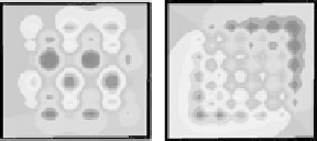
simulation input, two types of information were prerecorded into the top and
bottom layers of 3D recording media with a net thickness of 50 nm (Figure 6.12a).
The ''softness'' of a patterned SUL was controlled via continous variation of
SUL's bias current, as defined above. The respective signal profiles, read back at
biasing current values of 5.85 and 1.56 A-turn, respectively, (Figure 6.12b) indeed
Parallel set of signals read back
at I
bias
= 5.85 and 1.56 (A turn)
Top layer
Bottom layer
(a)
(b)
Figure
6.12.
(a) Prerecorded magnetization in the top and bottom layers of a
20-layer recording media. (b) Sets of signals read back at a SUL's biasing current
of 5.85 and 1.56 A-turn.


Search WWH ::

Custom Search