Information Technology Reference
In-Depth Information
H
z
(Oe)
50000
45000
40000
35000
30000
25000
20000
15000
10000
Bottom and
top surfaces
of the recording layer
Curv 1
Head
Recording
layer
SUL
ABS surface of
the recording head
Curv 2
Curv 3
Flat
−
20246
8 0 2 4 6
Distance across the thickness (nm)
(a)
Z-axis
Recording head
Recording head
Offset
b
b
Field
profile line
Recording layer
Field
profile line
a
a
L
X-axis
L
X-axis
SUL
SUL
P
(side band)
P
(side band)
T
(period)
T
(period)
(b)
(c)
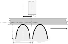
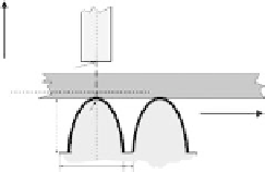
Figure
6.10.
(a) The perpendicular recording field versus the distance along the
line from the top surface of the SUL to the air bearing surface of the head for
three different values of the curvature of the semispherical island in the SUL type
under study. For comparison, an equivalent dependence for a regular flat SUL is
also shown. Diagrams showing the location of the recording head with respect to
an island in the convex patterned SUL (b) with the head and the island perfectly
centered and (c) with a half-period offset line between the head and the island.
be achieved via sequential recording from the bottom up via continuous variation
of the current in the drive coil. Patterning of SUL provides another knob to
control the recording field. As seen in Figure 6.10a, at a given value of the current,
the field maximum could be shifted from the bottom to the top side of the
recording layer via variation of the softness of SUL. Moreover, the investigators
propose to use soft interlayers (SIL) to separate magnetic layers across the
thickness. As illustrated below, the use of SILs is expected to facilitate recording
across the thickness substantially, thus further increasing the number of distin-
guishable signal levels.
Profiles of the simulated recording field along a track line in the recording
layer 2.5 nm away from the top surface of SUL (Figure 6.10b, c) for a patterned


Search WWH ::

Custom Search