Information Technology Reference
In-Depth Information
Real head
Recording layer
S
real
δ
Central plane of the
recording layer
S
image
'Image' head
SUL
Note: Spacing loss due to the SUL is
S
image
−
S
real
=
.
δ
(a)
Real head
SUL boundary
Recording
layer
H
H >
Image head
SUL
SUL
(b)
Disk substrate
Pattern
Rotation
direction
(c)
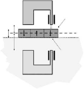
Figure
6.8.
(a) A diagram of an image model to illustrate the spacing loss due to
the offset in the separation between the real and image heads with respect to
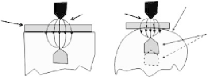
the central plane of the recording layer. (b) A schematic illustrating the ''move''
of the image closer to the recording layer if a convex SUL boundary is used.
(c) Patterned SUL with rectangular islands.


Search WWH ::

Custom Search