Information Technology Reference
In-Depth Information
Since the value is larger for the noncircumferential case, stable trapping of
diagonal interconnects should be possible. (There is suggestive experimental
data that stable diagonal interconnects can indeed be achieved [14], although
the substrate in that case was dried before imaging.) Moreover, since K
?
K
jj
,a
short field burst perpendicular to an existing wire should not disrupt it.
5.4.2. 2
2 Crossbar
We can perform a similar, albeit more entailed, analysis to determine the
feasibility of stable noncircumferential interconnects in larger crossbars, such as
the 2
2 geometry we now consider.
For the specific octagonal electrode tip geometry and voltages shown in
Figure 5.12, we can calculate all force values (F
r
E
2
):
3
2
2
1
2
a
1
2
þ
a
2
F
2
F
1
¼
F
3
F
1
¼
2
ðÞ
F
4
F
1
¼
3
:
;
#
3
;
"
r
1
2
þ
p
3
1
p
2
2
p
ð
1
p
Þ
2
1
2
þ
a
2
p
2
F
4
F
1
¼
F
5
F
1
¼
2
ðÞ
#
3
;
i
3
;
"
h
r
1
2
þ
p
p
2
2
þ
1
In order to estimate the proper conditions for trapping of non-circumferential
interconnects, particularly the interconnect at F
1
, we are most interested in the
+
V/2
+
V/2
F
2
F
1
L
aV
aV
F
4
F
3
F
5
−
aV
−
aV
pL
V/2
V/2
−
−
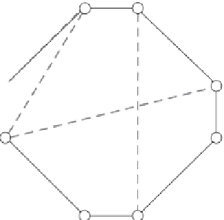
Figure
5.12.
Schematic diagram for dielectrophoretic force constants for various
interconnects in a 22 crossbar geometry. Circles indicate electrode tips.


Search WWH ::

Custom Search