Information Technology Reference
In-Depth Information
Sum0
Sum1
Sum2
Sum3
−
1.00
Cout
A0
B0
A1
B1
A2
B2
A3
B3
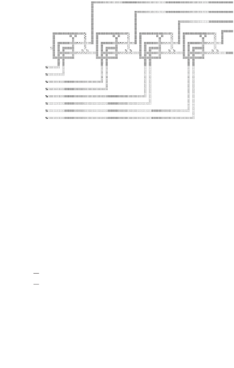
Figure
4.21.
Layout of a 4-bit QCA ripple-carry adder.
In an actual layout, the latency may be larger because the long interconnects
associated with the most significant carries would have to be divided into more
than one clocking zone. The advantages of carry-look-ahead adders are dependent
on the ability to realize AND and OR gates with more than two inputs. A ripple-
carry adder is considered the slowest bit-parallel adder design in CMOS circuits.
However, the QCA ripple-carry adder has better performance when compared to
both the QCA carry-look-ahead and carry-select adder designs because of the
inherent pipelining associated with QCA technology.
4.11.2. QCA Multiplication
A constant coefficient multiplier has been implemented using the adders described
above [56]. The block schematic for a 2-bit multiplier is shown in Figure 4.23. The
A1
B1
P1
Critical path
P4
A1
B1
C0
S4
G1
P2
G2
P3
G3
C4
P4
G4
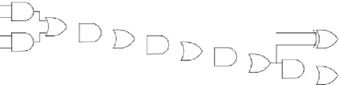
Figure
4.22.
Critical path of a 4-bit QCA carry-lookahead adder from the input of
the first bit to the carry output C
4
or the sum output S
4
.


Search WWH ::

Custom Search