Environmental Engineering Reference
In-Depth Information
the most suitable phase for formulating the second consti-
tutive relationship. The water phase constitutive relationship
describes the change in the volume of water present in the
referential soil structure element under various stress condi-
tions. Water is assumed to be incompressible and the equation
accounts for the net inflow or outflow of water from the
element. The water phase constitutive relationship can be for-
mulated in a semiempirical manner on the basis of a linear
combination of the stress state variables. The incremental
constitutive equation for the water phase can be written as
d
u
a
−
u
w
H
w
E
w
d
σ
mean
−
u
a
+
dV
w
V
0
=
3
(13.29)
where:
(a)
E
w
=
water volumetric modulus associated with a change
in
σ
mean
−
u
a
and
H
w
=
water volumetric modulus associated with a change
in
u
a
−
u
w
.
The summation of water volume changes for each incre-
ment in stress state gives the final change in the volume of
water:
dV
w
V
0
V
w
V
0
=
(13.30)
13.3.3 Change in Volume of Air
Changes in the volume of air in an element can be computed
as the difference between the soil structure and water volume
changes. The continuity requirement can also be written in
an incremental form using volumetric strain change
dε
v
:
(b)
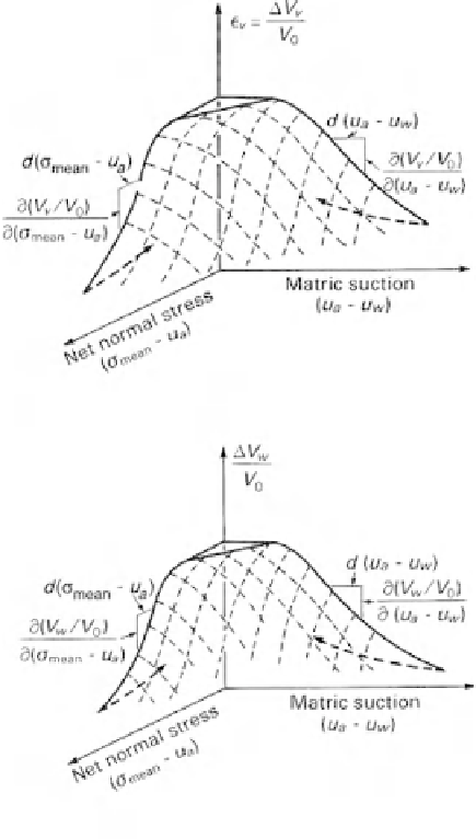
Figure 13.8
Three-dimensional constitutive surfaces for unsatu-
rated soil: (a) soil structure constitutive surface; (b) water phase
constitutive surface.
dV
w
V
0
+
dV
a
V
0
dε
v
=
(13.31)
z-
directions. The formulations can also be applied to special
loading conditions as depicted in Fig. 13.9. The constitutive
equations for various types of loading conditions can be
derived from general strain-stress formulations.
The constitutive relationships for an unsaturated soil can
be presented graphically in the form of constitutive surfaces
(Fig. 13.8). The deformation state is plotted with respect
to the
σ
mean
−
u
a
and
u
a
−
u
w
stress state variables. The
coefficients used in the constitutive equations are the slopes
of the constitutive surface at a point. The slopes must be
defined with respect to both axes. For example, the slopes
of the soil structure constitutive surface at a point are equal
to 3
(
1
13.3.4 Isotropic Loading
The total stress increments are equal for isotropic loading
in three directions (i.e.,
dσ
x
=
dσ
y
=
dσ
z
=
dσ
3
). No shear
stresses are developed in the soil mass under isotropic load-
ing conditions. Substituting the conditions associated with
isotropic loading into Eq. 13.26 gives the soil structure con-
stitutive equation:
2
μ) /E
and 3
/H
with respect to
σ
mean
−
u
a
and
u
a
−
u
w
, respectively (Eq. 13.26 and Fig. 13.8a). The coef-
ficients on the constitutive surface are referred to as “vol-
umetric deformation coefficients.” These coefficients vary
from one stress state to another for a curved or nonpla-
nar constitutive surface. Similarly, the slopes on the water
phase constitutive surface at a point are 3
/E
w
and 1
/H
w
with respect to the stress variables
σ
mean
−
u
a
and
u
a
−
u
w
,
respectively (Eq. 13.29 and Fig. 13.8b).
The above constitutive relations can be formulated for
a general,
−
3
1
d
σ
3
−
u
a
+
H
d
u
a
−
u
w
(13.32)
−
2
μ
E
3
dε
v
=
where:
three-dimensional
loading in the
x-, y-,
and
σ
3
=
total isotropic stress.


Search WWH ::

Custom Search