Environmental Engineering Reference
In-Depth Information
For the first iteration, the factor of safety
F
s
in the normal
force equation can be set to 1.0 or estimated from the ordi-
nary method (Fredlund, 1987). The interslice shear forces
can be set to 0.0 for the first iteration when computing the
normal force. The computed normal force is then used to
calculate the factors of safety with respect to moment and
force equilibriums (i.e.,
F
m
and
F
f
).
The next step is to compute the interslice normal forces
E
L
and
E
R
in accordance with Eq. 12.89. There are two sets
of interslice force calculations: one associated with moment
equilibrium and the other associated with force equilibrium.
The interslice shear forces in Eq. 12.75 can be set to zero for
the first iteration. The computed interslice normal forces
E
L
and
E
R
can then be used in the calculation of the interslice
shear forces
X
L
and
X
R
for each slice according to Eq.
12.91. The selected interslice force function along with a
specified
λ
value is used during the iterative procedure until
convergence is achieved.
The computed moment equilibrium factor of safety
F
m
and the corresponding interslice forces are used to recalcu-
late new values for the normal force
N
and the moment of
equilibrium factor of safety
F
m
. The updated values for the
normal force
N
and the moment equilibrium factor of safety
F
m
are then used to revise the interslice normal forces and
interslice shear forces (i.e.,
E
L
,
E
R
,
X
L
, and
X
R
) associated
with moment equilibrium. The computed force equilibrium
factor of safety
F
f
and the corresponding interslice forces
from the first iteration are used to revise the magnitudes of
the variables
N, F
f
,
E
L
,
E
R
,
X
L
, and
X
R
associated with
force equilibrium.
Calculations are stopped when the difference in the factor
of safety between two successive iterations is less than the
desired tolerance. When the solution has converged, moment
and force equilibrium factors of safety corresponding to
the selected interslice force function
f(x)
and the selected
λ
value are obtained. The analysis can proceed using the
same interslice force function
f(x)
but varying the
λ
value.
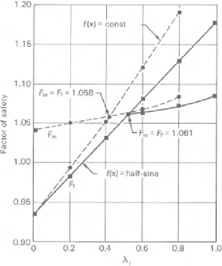
Several factor of safety values
F
m
and
F
f
associated with
different
λ
values can be obtained and plotted as shown
in Fig. 12.77. The moment equilibrium factor of safety
F
m
does not vary significantly with respect to the
λ
values for
circular slip surfaces. The force equilibrium factor of safety
F
f
varies with
λ
values for a circular slip surface. Curves
joining the
F
m
and
F
f
data intersect at a point where total
equilibrium (i.e., moment and force equilibrium) is satisfied.
Figure 12.77
Variation of moment and force equilibrium factors
of safety with respect to
λ
.
It is most practical and appropriate to perform an inde-
pendent analysis for the assessment of the pore-water and
pore-air pressures. The computed pore pressures can then be
imported into the slope stability analysis as a grid of desig-
nated values, as shown in Fig. 12.78. Pore-water pressures
can be either positive or negative and an interpolation tech-
nique can be used to obtain the pore-water pressure at any
designated point (e.g., the base of a slice).
Piezometric lines can also be used to designate the pore-
water pressures in a slope (Fig. 12.79). However, care must
be exercised when using a piezometric line to designate neg-
ative pore-water pressures. The vertical distance from the
piezometric line down to a point below the line is equal
to the positive pore-water pressure head (i.e.,
u
w
=
h
w
ρ
w
g
).
On the other hand, the vertical distance from the piezomet-
ric line up to a point above the line can be considered as the
negative pore-water pressure head [i.e.,
u
w
(
h
w
ρ
w
g
].
The use of a piezometric line can lead to pore-water pres-
sures which are in considerable error when slopes are steep
and the gradient along the water table is high.
−
)
=
12.5.13 Relationship between GLE and Other
Methods of Slices
The GLE method of slices can be specialized to corre-
spond to various limit equilibrium methods. The various
methods of slices can be categorized in terms of the condi-
tions of static equilibrium satisfied and the assumption used
with respect to the interslice forces. Table 12.7 summarizes
the conditions of static equilibrium satisfied by the various
12.5.12 Input of Pore-Water and Pore-Air Pressures
Several procedures have been used to designate the pore-
water pressures when performing a slope stability analysis
where saturated soils are involved. Some of the suggested
procedures are not appropriate when using unsaturated soils
with negative pore-water pressures. For example, the pore
pressure coefficients
r
u
become a negative value that tends
to negative infinity as the ground surface is approached.


Search WWH ::

Custom Search