Environmental Engineering Reference
In-Depth Information
provides coverage of all possible circular geometries. When
the slip surface takes on a composite shape (i.e., part circular
and part linear), it is still possible to use a grid of centers and
varying radii to search for the critical slip surface (Fredlund,
1981a). In addition, a general shape can also be assumed using
a series of straight lines to define the slip surface.
Various automatic search routines have been programmed
to reduce the number of computations. Some routines start
with an assumed center and seek to find the critical center
by moving in a zigzag manner (Wright, 1974). Others use
an initially coarse grid of centers which rapidly converge to
a critical center (Fredlund, 1981a).
There is probably no analysis conducted by geotechni-
cal engineers which has received more attention than the
limit equilibrium methods of slices for the computation of
the factor of safety (Fredlund, 1980a). The limit equilib-
rium method of slices has proved to be a useful and reliable
tool for assessing the stability of a slope. Its “track record”
is impressive for cases where the shear strength proper-
ties of the soil and the pore-water pressure conditions have
been adequately assessed (Sevaldson, 1956; Kjaernsli and
Simons, 1962; Skempton and Hutchinson, 1969; Chowd-
hury, 1980). The limit equilibrium methods of slices require
a limited amount of computer input but can quickly perform
extensive trial-and-error searches for the critical slip surface.
has been widely adopted in limit equilibrium methods (Fred-
lund and Krahn, 1977). The various limit equilibrium slope
stability methods that assume a direction for the interslice
forces have been shown to be special cases of the GLE
method (Fredlund et al., 1981).
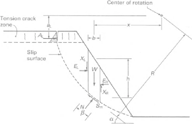
Calculations for the stability of a slope are performed by
dividing the soil mass above the assumed slip surface into
vertical slices. The forces acting on a slice within the sliding
soil mass are shown in Fig. 12.72 for a composite slip sur-
face. The forces are designated for a unit width (i.e., direction
perpendicular to movement) of the slope. The variables are
defined as follows:
W
=
total weight of the slice of width
b
and height
h
,
N
=
total normal force on the base of the slice,
S
m
=
shear force mobilized on the base of each slice,
E
=
horizontal interslice normal forces (the
L
and
R
sub-
scripts designate the left and right sides of the slice,
respectively),
X
=
vertical interslice shear forces (the
L
and
R
subscripts
designate the left and right sides of the slice, respec-
tively),
R
=
radius for a circular slip surface or the moment arm
associated with the mobilized shear force
S
m
for any
shape of slip surface,
f
=
perpendicular offset of the normal force from the cen-
ter of rotation or from the center of moments,
12.5.5 General Limit Equilibrium Method
The GLE method provides a general theory wherein other
methods can be viewed as special cases. These elements
of statics along with the failure criterion are insufficient to
make the slope stability problem determinate (Morgenstern
and Price, 1965; Spencer, 1967). Either additional elements
of physics or an assumption regarding the direction or mag-
nitude of some of the forces is required to render the prob-
lem determinate. The GLE method utilizes an assumption
regarding the direction of the interslice forces. This approach
x
=
horizontal distance from the centerline of each slice
to the center of rotation or to the center of moments,
h
=
vertical distance from the center of the base of each
slice to the uppermost line in the geometry (i.e., gen-
erally ground surface),
a
=
perpendicular distance from the resultant external
water force to the center of rotation or the center of
moments (the
L
and
R
subscripts designate the left
and right sides of the slope, respectively),
Figure 12.72
Forces acting on one slice of a sliding mass with a composite slip surface.


Search WWH ::

Custom Search