Environmental Engineering Reference
In-Depth Information
wall and the pore-water pressure distribution is assumed to
be hydrostatic. It can be seen that the passive earth force in
this case is less sensitive to suction changes than when the
suction is a constant value with respect to depth.
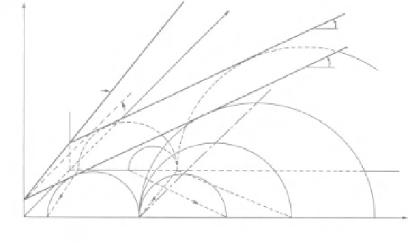
depth can be visualized using an extended Mohr-Coulomb
diagram (Fig. 12.61). Circle
A
shows the net vertical and net
horizontal pressures at a depth
y
for the active pressure state.
Matric suction decreases as the water content in the soil
increases. The horizontal pressure will follow a stress path
over to the stress circle
A
1
under unrestricted movement of
the wall. The magnitude of the pressure against the wall is
increased to the active pressure state for a saturated soil.
Let us suppose, on the other hand, that the retaining struc-
ture is fixed and the initial stress state is represented by the
at-rest condition shown by circle
C
. As the soil becomes
wet and the matric suction decreases, the horizontal pressure
change will follow the stress path to circle
C
1
. The horizon-
tal pressure becomes greater than the vertical pressure at this
point.
Let us also consider the possibility where the initial at-rest
coefficient of earth pressure is 1.0. The stress changes in the
soil could now follow a path to circle
D
1
where the final
12.3.17 Effect of Changes in Suction on Active
and Passive Earth Pressure
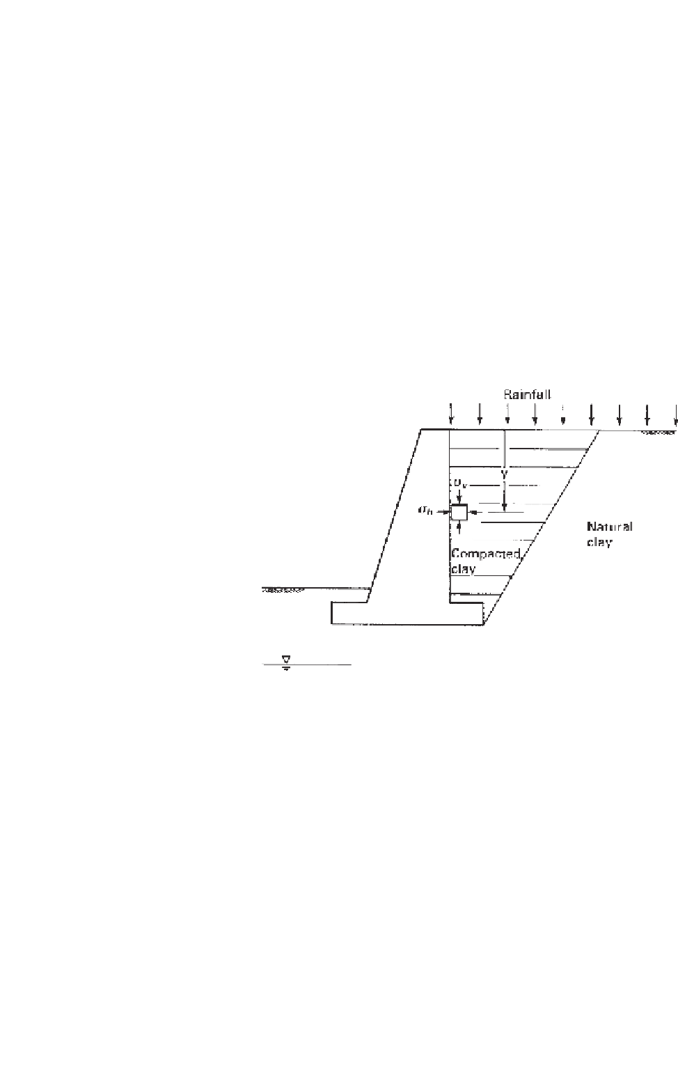
Changes in the environment may result in water entering the
retaining wall backfill. The water results in a change in the
active or passive pressure. A decrease in matric suction results
in an increase in the pressure against the wall for the active
earth pressure case. The magnitude of the pressure developed
depends on whether the wall moves in response to the pres-
sure change. If the wall cannot move or does not move by
a sufficient amount, the pressure developed against the wall
can become even greater than the computed active pressure
corresponding to the saturated soil case.
Let us consider compacted clay placed behind a retaining
wall as shown in Fig. 12.60. Changes in stresses at a specific
Figure 12.60
Use of clay as backfill material behind retaining wall.
φ
′
φ
′
b
φ
A
c
D
1
σ
v
A
1
c
1
C
′
σ
h
(
a
)
σ
v
σ
h
(
c
)
σ
h
(
d
)
σ
hp
σ
v
-
u
a
Figure 12.61
Lateral pressures on wall that is restricted to limited or no movement.


Search WWH ::

Custom Search