Environmental Engineering Reference
In-Depth Information
Figure 12.52
Stress paths for Rankine active and passive earth pressure conditions.
conditions. Little research has been done on this subject for
unsaturated soils.
shape of the slip surface is changed and is dependent upon
the vertical movement of the wall as well as the horizontal
movement when friction is considered along the wall. Only
the case of an unsaturated soil placed against a smooth, verti-
cal wall is considered in this chapter. The analysis of frictional
walls in unsaturated soils is essentially the same as those for a
saturated soil. The difference in analyzing a wall adjacent to
saturated and unsaturated soils lies mainly in the fact that
cohesion has a component related to matric suction in an
unsaturated soil.
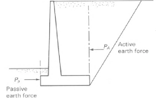
12.3.14 Total Lateral Earth Force
Retaining walls serve to retain the backfill placed behind the
wall (Fig. 12.53). The earth pressure tends toward the at-
rest pressure state if the wall is fixed. However, movement
of the wall away from the soil gives rise to the develop-
ment of the active earth force against the wall. Movement
of the wall into the soil results in the development of the pas-
sive earth force against the wall. If the wall is vertical and
smooth, the lateral force is equal to the sum of the active
(or passive) pressures at all depths. There may be an active
earth force developed against one side of the wall and a pas-
sive earth force developed against the other side, as shown
in Fig. 12.53.
Analyses such as those proposed by Coulomb can be used
when friction is considered between the soil and the wall. The
12.3.15 Active Earth Force
The active earth force
P
A
against a smooth wall is equal to the
active earth pressure integrated from the bottom of the tension
zone depth
y
t
to the bottom of the wall
H
. The integration
of the active pressure equation over the entire depth gives
the total active force. The upper portion of the net pressure
diagram is in a state of tension. It can be assumed that the soil
in this zone cannot adhere to the retaining wall. Figure 12.54
illustrates the components of the pressure diagram and the
limits of integration on the active pressure diagram:
H
P
A
=
p
a
dy
(12.57)
yt
The depth of the tension cracks,
y
t
, must be less than
H
in order for there to be a positive total force on the wall.
Let us consider the case where matric suction is a constant
value with respect to depth:
H
H
2
c
dy
N
φ
ρgydy
N
φ
P
A
=
−
y
t
y
t
H
u
w
)
ta
n
φ
b
dy
N
φ
2
(u
a
−
−
(12.58)
Figure 12.53
Approximations of earth pressures acting on a
retaining wall.
y
t


Search WWH ::

Custom Search