Environmental Engineering Reference
In-Depth Information
Load cell
Load cell
Inner cell
Outer cell
Outer cell
Inner cell
water level
Reference
water level
Inner cell
Figure 11.39
Double-walled triaxial cell to increase accuracy in
measuring total volume change of soil specimen.
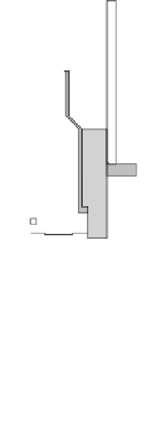
Figure 11.40
Double-walled triaxial cell that uses differential
pressure measurements to determine total volume change of soil
specimen. (Courtesy of GDS Instruments, London.)
Successful cell fluid measurements have been made using
mercury as the cell fluid (Bishop et al., 1960). These mea-
surements were also made using a double-walled triaxial
cell in a temperature-controlled room. However, mercury is
hazardous to health and its use should be avoided. Fluids
other than mercury have also been used in conjunction with
double-walled triaxial cells, as shown in Fig. 11.39 (Wheeler
and Sivakumar, 1992).
There have been ongoing attempts to further improve mea-
surements of total volume change of unsaturated soil speci-
mens. One such system was developed at Hong Kong Uni-
versity of Science and Technology and later manufactured
by GDS Instruments (GDS Instruments, 2011). Figure 11.40
shows how a double-walled cell can be used in conjunction
with an accurate differential pressure transducer to mea-
sure soil specimen volume changes. The differential pressure
transducer measures changes in water level between a ref-
erence water level and fluctuations in a reduced-diameter
cylinder surrounding the vertical piston. The system shown
in Fig. 11.40 is presently marketed by GDS Instruments,
London.
The overall volume change of a triaxial soil specimen has
also been attempted by independently measuring the vertical
deflection and radial deformation of the specimen during
the test. The vertical deflection of the soil specimen can
be measured using a conventional dial gauge or an LVDT
(i.e., linear variable differential transformer). LVDTs have
accuracy comparable to that of dial gauges. Some LVDTs
can be submerged in oil or water. Various applications of
LVDTs in triaxial testing are described by Head (1986).
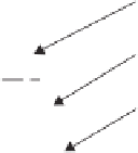
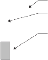
Noncontacting transducers have been used during triax-
ial testing programs (Cole, 1978; Khan and Hoag, 1979;
Drumright, 1987). The device consists of a sensor and an
aluminum target (Fig. 11.41). The sensor is a displacement
transducer clamped to a post and connected to the electronic
measuring system through a port in the base plate. The alu-
minum target can be attached to the rubber membrane (e.g.,
using silicon grease), near the midheight of the specimen.
Three sensors and targets can be placed around the circum-
ference of the specimen at 120
◦
intervals (Fig. 11.41).
The noncontacting transducers operate on an eddy current
loss principle. An eddy current is induced in the aluminum
target by a coil in the sensor. The magnitude of the induced
eddy current is a function of the distance between the sen-
sor and the aluminum target. The distance changes between
the aluminum target and the sensor as the specimen deforms
laterally. The distance change causes a change in the mag-
nitude of the generated eddy current. Impedance in the coil
changes, resulting in a change in the DC voltage output.
Another system that has proven to work well involves the
use of a combined radial and axial set of LVDTs, as shown
in Fig. 11.42. The measuring system is clamped onto the
soil specimen near midheight. The average axial strain is


Search WWH ::

Custom Search