Environmental Engineering Reference
In-Depth Information
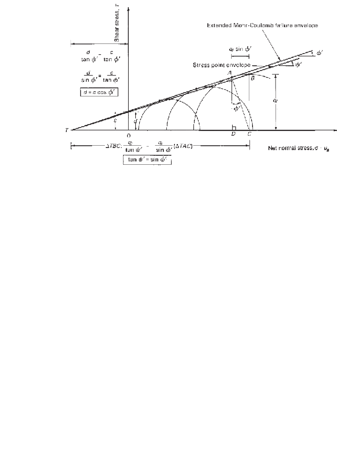
Figure 11.15
Relationships between
c, d
,
φ
,and
ψ
.
The above equation can be rearranged by substituting
distance between points
T
and
O
(i.e.,
TO
):
Eq. 11.24 for
d
and substituting
u
a
−
u
w
f
for
r
f
in order
to obtain the relationship between,
ψ
b
,
φ
b
, and
φ
:
d
tan
ψ
=
c
tan
φ
(11.22)
tan
ψ
b
tan
φ
b
cos
φ
=
(11.26)
Substituting Eq. 11.21 into Eq. 11.22 and rearranging
Eq. 11.22 yields
The above relationships can be used to define the
stress point envelope corresponding to an extended Mohr-
Coulomb failure envelope or vice versa. The extended
Mohr-Coulomb failure envelope can be established by test-
ing a soil under saturated and unsaturated conditions. The
Mohr-Coulomb failure envelope for the saturated condition
gives the angle of internal friction
φ
and the effective
cohesion
c
.
The cohesion intercept
c
can be obtained from a single
Mohr circle if a planar failure envelope is assumed at an
angle
φ
and the matric suction is known. Figure 11.17 illus-
trates the construction of a Mohr circle at failure with its
corresponding
p
f
and
q
f
values. A failure envelope with a
slope angle
φ
is drawn tangent to the Mohr circle at point
A
. The envelope intersects the shear strength axis at point
B
and the
σ
c
cos
φ
d
=
(11.23)
When matric suction at failure is equal to zero (i.e., the
saturated condition), Eq. 11.23 becomes
d
=
c
cos
φ
(11.24)
Figure 11.16 shows the intersection lines of the extended
Mohr-Coulomb failure envelope and the stress point
envelope on the shear strength versus matric suction plane.
The intersection lines associated with the extended Mohr-
Coulomb failure envelope and the stress point envelope
are defined by Eqs. 11.12 and 11.18, respectively. The
ratio between the
d
and
c
values is always constant and
equal to cos
φ
(i.e., Eq. 11.23) at various matric suctions.
As a result, the difference between the
d
and
c
values
is not constant for different matric suctions. In other
words, the intersection lines are not parallel, or put another
way,
φ
b
u
a
axis at point
T
. The cohesion intercept
c
is
computed from triangle
TBO
(Fig. 11.17):
−
p
f
tan
φ
q
f
sin
φ
−
c
=
(11.27)
ψ
b
. Substituting Eq. 11.12 and Eq. 11.18 into
Eq. 11.23 gives the following relationship:
=
Rearranging Eq. 11.27 gives
c
cos
φ
+
u
a
−
u
w
f
tan
φ
b
cos
φ
.
(11.25)
d
+
r
f
tan
ψ
b
=
q
f
cos
φ
−
p
f
tan
φ
c
=
(11.28)


Search WWH ::

Custom Search