Environmental Engineering Reference
In-Depth Information
saturated soil mechanics (Lambe and Whitman, 1979). The
K
f
line passes through the top points of the Mohr circles
for saturated soils at failure. The
K
f
line has a slope angle
ψ
with respect to the
p
axis and an ordinate intercept
d
on
the
q
axis. Any line parallel to the
K
f
line on the planar
stress point envelope will have a slope angle
ψ
with respect
to the
p
axis. The stress point envelope reverts to the
K
f
line as the soil becomes saturated or when matric suction
r
f
becomes equal to zero.
The intersection line between the stress point envelope
and the
q-
versus-
r
plane has a slope angle
ψ
b
with respect
to the
r
axis (Fig. 11.14b). The intersection line indicates
that there is an increase in strength as the matric suction at
failure,
r
f
, increases. The equation for the intersection line
can be written as follows:
d
+
r
f
tan
ψ
b
d
=
(11.18)
where:
d
=
ordinate intercept of the stress point envelope on the
q
axis at a
r
f
and
p
f
value equal to zero.
The ordinate intercept of the stress point envelope on the
q-
versus-
r
plane is equal to
d
when
r
f
is zero. The ordinate
intercept is equal to
d
(i.e., Eq. 11.18) when
r
f
is not zero.
The above variables,
d
,
ψ
, and
ψ
b
, are the required param-
eters for Eq. 11.18. The stress point envelope can also be
represented by contour lines when the surface is projected
onto the
q-
versus-
p
plane. The equation for the contour lines
is obtained by substituting Eq. 11.18 into Eq. 11.17:
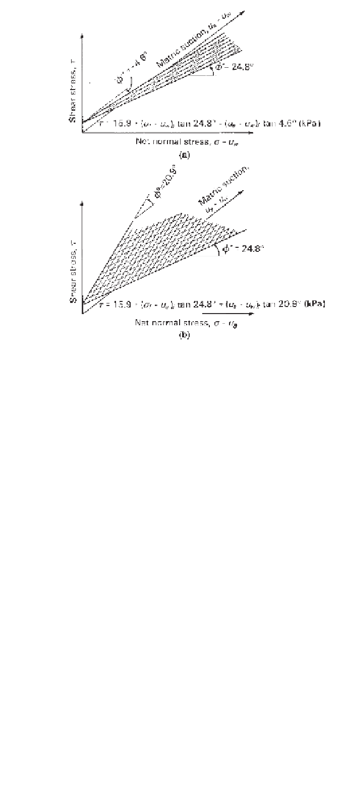
Figure 11.13
Extended Mohr-Coulomb failure envelope plotted
with respect to two possible combinations of stress state variables:
(a) failure envelope defined in terms of
σ
−
u
w
and
u
a
−
u
w
stress
state variables; (b) failure envelope defined in terms of
σ
−
u
a
and
u
a
−
u
w
stress state variables.
tan
ψ
q
f
=
d
+
p
f
(11.19)
σ
1
f
=
major principal stress at failure,
The stress point envelope can be related to the extended
Mohr-Coulomb failure envelope by obtaining the relation-
ships between the parameters used to define both envelopes
(i.e.,
c
,
φ
,
φ
b
and
d
,
ψ
,
ψ
b
). Figure 11.15 presents Mohr
circles on the
τ
versus
σ
σ
3
f
=
minor principal stress at failure,
d
=
intercept of the stress point envelope on the
q
axis
when
p
f
and
r
f
are equal to zero,
=
σ
1
+
σ
3
/
2
u
a
f
; mean net normal stress at
p
f
−
u
a
) plane for a specific matric
suction. The extended Mohr-Coulomb failure envelope is
drawn tangent to the Mohr circles (e.g., at point
A
), whereas
the stress point envelope passes through the top points of the
Mohr circles (e.g., through points
B
). The extended Mohr-
Coulomb failure envelope and the stress point envelope have
slope angles of
φ
and
ψ
, respectively, with respect to
the
σ
−
failure,
ψ
=
slope angle of the stress point envelope with
respect to the stress variable
p
f
,
matric suction at failure [i.e.,
u
a
−
u
w
f
], and
r
f
=
ψ
b
=
slope angle of the stress point envelope with
respect to the stress variable
r
f
.
u
a
axis. The distance
b
etween the tangent point
A
and the top point
B
(i.e.,
AB
) can be computed from
triangle
ADC
as being equal to
q
f
sin
φ
. The radius
q
f
decreases and eventually goes to zero as the Mohr circle
moves to the left. As a result, the distance between the
tangent and the top points (i.e.,
q
f
sin
φ
) also decreases
and eventually goes to zero. This means that the extended
Mohr-Coulomb failure envelope and the stress point enve-
lope converge to a common point on the
σ
−
Figure 11.14b presents a planar stress point envelope cor-
responding to the planar extended Mohr-Coulomb failure
envelope shown in Fig. 11.14a. Equation 11.17 defines the
stress point envelope. The frontal planes shown in Fig. 11.14
represent the saturated condition where matric suction is
zero. As a result, the
σ
1
+
σ
3
/
2
−
u
a
axis reverts to the
σ
1
+
σ
3
/
2
u
w
axis on the frontal plane. The intersec-
tion line between the stress point envelope and the frontal
plane is a line commonly referred to as the
K
f
−
−
u
a
axis (i.e.,
line in
point
T
).


Search WWH ::

Custom Search