Environmental Engineering Reference
In-Depth Information
three-layer system were maintained at constant values using
independent heat exchangers. The heat exchangers created
a constant vertical heat flux through the Pyrex disks and the
soil specimen.
The soil specimen and the Pyrex disks were surrounded
by a 50-mm-thick polystyrene jacket to reduce radial heat
losses. The temperatures at the top and bottom of the Pyrex
disks were recorded periodically until steady-state heat flux
conditions were established, as shown in Fig. 10.15 (Cote and
Konrad, 2005). The thermal conductivity of the soil specimen,
λ
, was determined from the temperature measurements at the
surfaces of the Pyrex disks along with the following equation:
Cold room
Insulated box
1 m × 1 m × 1 m
Heating bulb
Fan
λ
uf
h
T
1
2
T
uf
h
uf
+
T
lf
h
lf
λ
=
λ
lf
(10.31)
where:
Temperature-controlled fluid
h
=
distance
between
two
temperature
measure-
ments, m,
temperature difference,
◦
C,
T
=
thermal conductivity, W/m/
◦
C,
λ
=
uf
=
upper heat flux meter, and
lf
=
lower heat flux meter.
Heat exchanger
The Cote and Konrad (2005) apparatus was used for mea-
suring the thermal conductivity of both unfrozen and frozen
soil specimens. The temperature difference between the top
and the bottom of the soil specimen was about 8
◦
C, resulting
in a thermal gradient of 0.2-0.6
◦
C/cm. Figure 10.16 shows
typical thermal conductivity values measured on a variety of
coarse materials. The specimens were tested at various ini-
tial water contents. Figure 10.17 shows thermal conductivity
measurements on the same materials in a frozen state.
Pyrex
Sample
Insulation
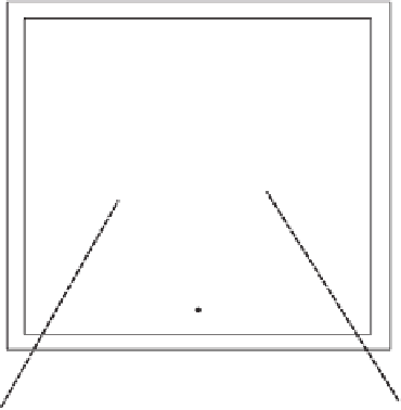
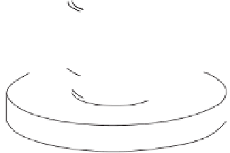
Figure 10.14
Experimental setup used to measure the thermal
conductivity of soils (after C ote and Konrad, 2005).
10.5.1.2 Use of Thermal Needle Probe
The use of a thermal needle probe to measure thermal con-
ductivity originated with Stalhane and Pyk (1931) and was
further developed by van der Held and van der Drunen
(1949). ASTM Designation D5334-08 (2008b) provides a
standard method for the measurement of thermal conduc-
tivity when using the thermal needle probe. The proposed
transient heating method can be used when the temperature
range is between 0 and 100
◦
C. The method fails once there
is a phase change involved.
Figure 10.18 shows the layout of the thermal needle
probe along with the electrical components used to apply a
constant current. The temperature change is measured with
respect to elapsed time. The needle probe must have a large
length-to-diameter ratio which is assumed to simulate an
infinitely long but thin heating source. The thermal needle
consists
by Cote and Konrad (2005) is described to illustrate the
procedure that can be used to measure the thermal conduc-
tivity of unfrozen as well as frozen soils.
Figure 10.14 shows the experimental apparatus used by
Cote and Konrad (2005) to measure the thermal conductivity
of a range of materials. The equipment consists of a thermal
conductivity cell surrounded with an insulated, temperature-
controlled box. The entire apparatus was placed in a room
where the temperature was maintained at 4
o
C. The cylin-
der had an inside diameter of 101.6 mm and a height of
75 mm. Soil specimens were placed between Pyrex disks
that were 30 mm in thickness. Each Pyrex disk had thermis-
tors embedded just below the top and bottom surfaces of
the disk. The thermal conductivity of the Pyrex disks was
1.015 W/m/
◦
Cat
of
a
stainless
steel
hypodermic
needle
which
20
◦
C. The
instrumented Pyrex disk acted as a heat flux meter. The tem-
perature boundary conditions at the top and bottom of the
20
◦
C and 1.090 W/m/
◦
Cat
−
+
contains a heater element and a thermocouple.
A known constant current is applied inside the needle and
the rise in temperature with time is monitored. The needle


Search WWH ::

Custom Search