Environmental Engineering Reference
In-Depth Information
The nodal flows above the assumed exit point are set at
zero while iterating toward a solution. The hydraulic heads
at or below the assumed exit point are specified as being
equal to the gravitational heads. After convergence, the pore-
water pressure head at the node directly above the assumed
exit point is examined. A negative pore-water pressure head
at this point indicates that the assumed exit point is correct.
Otherwise, the seepage face boundary needs to be revised by
assuming a higher exit point for the phreatic line. The above
procedure is repeated until the correct exit point is obtained.
The convergence of the solution to the correct exit point on
the downstream face adds one more degree of nonlinearity
that needs to be satisfied when using a numerical solution
for saturated-unsaturated seepage problems.
The above examples deal with seepage through earth
dams. However, steady-state analyses can be applied to
many other problems involving saturated-unsaturated flow.
perpendicular to the phreatic line. In this case, the lines
drawn normal to the phreatic line are equipotential lines.
Isobars are parallel to the phreatic line and this condition
is similar to that of the central section of a homogenous dam
shown earlier. The coefficient of permeability is essentially
independent of the pore-water pressure in the saturated zone.
Therefore, the saturated zone can be subdivided into several
flow channels of equal size. An equal amount of water (i.e.,
water flux
q
w
) flows through each channel. Lines separating
the flow channels are referred to as flow lines.
The water coefficient of permeability depends on the neg-
ative pore-water pressure or the matric suction in the unsat-
urated zone. The pore-water pressure decreases from zero
at the phreatic line to some negative value at ground sur-
face. Similarly, the permeability decreases from the phreatic
line to ground surface. Increasingly larger flow channels are
therefore required in order to maintain the same quantity of
water flow,
q
w
, as ground surface is approached.
The water flow in each channel is one dimensional, in
a direction parallel to the phreatic line. The coefficient of
permeability varies in the direction perpendicular to flow.
This condition can be compared to the previous case of
water flow through a vertical column. In the case of the
vertical column, the coefficient of permeability varied in the
flow direction and the equipotential lines were not equally
distributed throughout the soil column.
The above examples illustrate that equipotential lines
and flow lines intersect at right angles for unsaturated flow
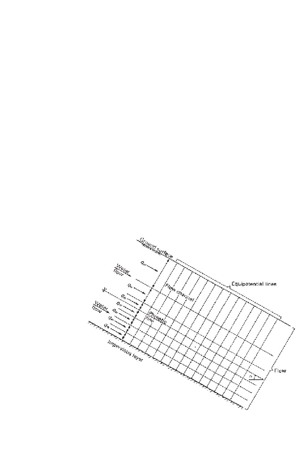
8.3.7 Example of Infinite Slope
A slope of infinite length is illustrated in Fig. 8.48. Let us
consider the case where steady-state water flow is estab-
lished within the slope and the phreatic line is parallel to
the ground surface. Water flows through both the saturated
and unsaturated zones and is parallel to the phreatic line.
The direction of the water flow indicates that there is no
flow perpendicular to the phreatic line. In other words,
the hydraulic head gradient is equal to zero in a direction
Figure 8.48
Saturated-unsaturated, steady-state seepage through infinite slope with impervious
lower boundary.


Search WWH ::

Custom Search