Environmental Engineering Reference
In-Depth Information
Figure 8.33
One-dimensional, steady-state water flow through an unsaturated soil with a
constant-head boundary condition.
v
wy
h
pn
h
wn
h
gn
h
wn
0.9
h
wn
0.8
h
wn
0.7
h
wn
0.6
h
wn
0.5
h
wn
Hydraulic
head,
h
w
h
pn
0.4
h
wn
h
gn
0.3
h
wn
Pore-water pressure
head,
h
p
0.2
h
wn
Gravitational
head,
h
g
y
0.1
h
wn
0
Datum
Water table
(
−
)
0
(+)
Head,
h
v
wy
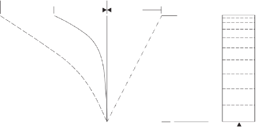
Figure 8.34
Steady-state evaporation from top of unsaturated soil column.
the negative pore-water pressure head at point
n
(i.e.,
h
pn
).
The hydraulic head boundary condition at the top and the
base of the soil column can be expressed mathematically as
follows:
The finite difference seepage equation can be written for
the
n
−
2 internal points (i.e., points 2, 3,
...
,
n
−
1). As a
result, there are
n
−
2 equations that must be solved simul-
taneously for
n
2 hydraulic heads at intermediate points.
The illustrated finite difference scheme is called an implicit
form. The equation is also nonlinear since the coefficients
of permeability
k
wy
are a function of matric suction, which
−
h
w
(
l
)
=
0
.
0 t
y
=
0
.
0 (base)
h
w
(n)
=
h
gn
+
h
pn
at
y
=
h
gn
(top)


Search WWH ::

Custom Search