Environmental Engineering Reference
In-Depth Information
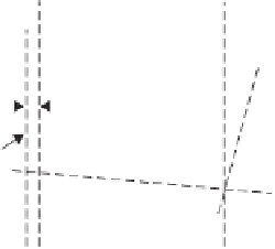
Fringing field
Electrode
Main field
Electrode
Access tube
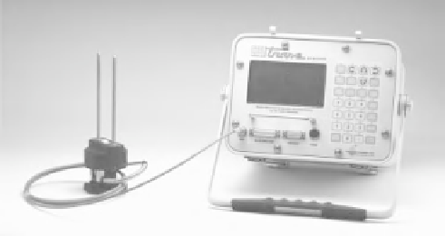
(a) Readout device for TRASE
Figure 4.91
Schematic of capacitance probe lowered into
access tube.
Rods
t
1
t
2
Several manufacturers produce capacitance-type sensors
that are used in a plastic access tube. For example, there is
a capacitor consisting of two hollow cylindrical metal elec-
trodes that are arranged coaxially but separated by several
millimeters by an insulating plastic (Fig. 4.91). An elec-
tronic oscillator is used to produce a sinusoidal waveform.
The capacitor forms part of the oscillating circuit and the
electrodes are arranged close to the inside of the access
tube. The intent is that the field of the capacitor will inter-
act with the soil outside the tube. The soil bulk permittivity
is measured and correlated with the water content of the soil.
There are a number of sensors that come within the capac-
itance or frequency-domain category. The Sentek Diviner
2000 and the Sentek Enviro-SCAN manufactured by Sen-
tek Sensor Technology are of the frequency-domain type.
Another capacitance-type sensor is the Delta-T PR1/6 sen-
sor. The capacitance-type sensors are practical and easy to
use for in situ monitoring of changes in water content in soil
cover systems and other near-ground-surface applications.
2048
Reference level
Cable
Soil
Inflection point
Propagation
step
"Dip"
Probe's
head
0
0
200
400
600
800
1000
1200
Point number
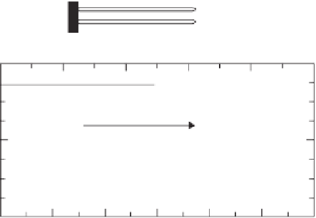
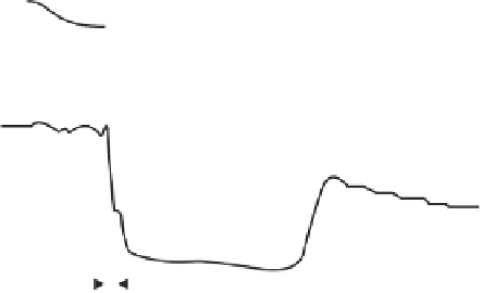
(b) Typical signal from TRASE reading
Figure 4.90
Characteristics of TRASE (manufactured by Soil-
moisture Corporation) signal using 30-cm-long rods (after Laurent,
1998).
the TDR method be calibrated for the specific soil where
measurements are being made. The oscilloscope electronic
system is quite costly and there have been attempts to develop
other technologies for the measurement of water content.
The result has been the development of a series of capaci-
tance sensor systems that still depend on the permittivity of
the soil.
4.5.3.3 Comparative Study on the Measurement
of Water Content
A comparative study involving highly plastic clay (i.e.,
Regina clay with a liquid limit of 74%) selected three
types of time-domain sensors and undertook to measure the
calibration curves. It was found that the measured volumetric
water contents differed considerably from the commonly
used calibration equation (Hu et al., 2010). The three types of
dielectric probes used in the study are known by their brand
names: CS616, ML2x, and SM200 (Fig. 4.92). The CS616
device is known as a water content reflectometry (WCR) sen-
sor (Hansson and Lundin, 2006). The ML2x (or Thetaprobe)
and SM200 devices are known as amplitude-domain
reflectometry sensors (Munoz-Carpena, 2004).
Clay soils have high electrical conductivity because of the
electrically charged clay colloids and the electrolytes in the
soil solution. The electrolytes affect the measurement of
the dielectric constant. The square root of the bulk dielectric
constant and the volumetric water content tested on Regina
4.5.3.2 Frequency-Domain Methodology
The frequency-domain or capacitance-type sensors measure
the dielectric constant using a single microwave (gigahertz)
frequency. A single open-ended coaxial cable is used that
has a single reflectometer at the end of the probe. The ampli-
tude and phase are measured at a particular frequency. The
device is generally calibrated in air and in blocks of material
and liquids with known dielectric constant properties.
A relatively small volume of soil is involved in the dielec-
tric constant measurement when using the frequency-domain
method. Consequently, the contact between the soil and the
probe becomes a critical factor. It has been suggested that
this method performs well in the laboratory but may be
subject to spatial variability in the field (Dirksen, 1999).


Search WWH ::

Custom Search