Environmental Engineering Reference
In-Depth Information
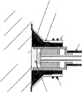
Water pressure
Porous ceramic disk
(15 bars)
Measuring water chamber
(0.1-2.5 mm)
Pressurizing cap
Epocast nine
15-bar ceramic
O-ring
Entran
transducer
Suction
probe
Stainless
steel
body
Strain gauge
Air vent
Electronic connection
Electronic connection
10 mm
Figure 4.15
Schematic of Imperial College, London, high-
suction range tensiometer (after Ridley, 1993).
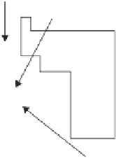
Figure 4.16
Schematic of University of Saskatchewan, Canada,
high-suction-range tensiometer (from Guan, 1996).
4.2.6.2 Design of Direct High-Suction Tensiometers
The Guan and Fredlund (1997b) direct high-suction ten-
siometer was developed independent of the research under-
taken at Imperial College by Ridley (1993). Although the
two research studies were independent, the outcome of the
studies was quite similar. Both studies produced similar
direct high-suction tensiometers and both used Entran pres-
sure transducers.
The Guan and Fredlund (1997b) direct high-suction ten-
siometer consisted of a high-range-pressure transducer (i.e.,
15,000 kPa) and a stainless steel shroud which was precisely
machined to embrace the transducer (Fig. 4.16). The sens-
ing area of the transducer had a smooth, circular surface
with a diameter of 7.0 mm. A 15-bar high-air-entry ceramic
disk was fitted into the shroud. Shrouds of different sizes
were manufactured and tested. The transducer and shroud
were assembled while being held under water. The separa-
tion between the pressure transducer and the ceramic disk
ranged from 0.1 to 0.5 mm.
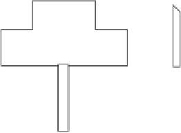
A mini direct high-suction probe was also developed at
Nanyang Technological University in Singapore by Meilani
et al., (2002). The suction probe used a 1500-kPa minia-
ture PDCR-81 pressure transducer manufactured by Druck
(Leicester, England). The miniature pressure transducer was
able to operate under water. The suction probe was placed
in a steel tube as shown in Fig. 4.17. The miniature suc-
tion probe consisted of a 0.09-mm-thick silicon diaphragm
mounted within 1.2mm of a 5-bar high-air-entry disk. The
high-air-entry disk was ground to a thickness of only 1.0mm
in order to achieve a rapid response when measuring nega-
tive pore-water pressures. The probe had negligible weight
(i.e., 3 g) and could be mounted on the side of a triaxial
soil specimen. The ceramic disk was glued in place using
Araldite 2021 epoxy.
Three miniature direct high-suction sensors were mounted
along the side of a triaxial specimen as shown in Fig. 4.18.
Silicone rubber grommet
Rubber membrane
Latex rubber to seal the rubber
membrane and grommet
Mini suction probe
Specimen
O-ring
5-bar high-air-entry ceramic disk
Figure 4.17
Schematic of Nanyang Technological University,
Singapore, mini high-suction-range tensiometer
(from Meilani
et al., 2002).
Matric suction measurements were made as the triaxial spec-
imen was slowly sheared to failure.
Several laboratory research studies have led to conclusions
on a number of issues that need to be given careful consider-
ation when designing a direct high-suction sensor. Marinho
and Chandler (1994) stated that the following factors could
affect the successful performance of a direct high-suction
sensor:
1. The water and all surfaces internal to the high-suction
sensor must be pure and clean (Henderson and Speedy,
1980).
2. The surfaces in contact with the internal water system
must be smooth in order to reduce or avoid the num-
ber and size of small crevices that could initiate the
cavitation process.


Search WWH ::

Custom Search