Environmental Engineering Reference
In-Depth Information
condition on the horizontal plane is represented by the stress
point
σ
1
−
the vertical and horizontal planes (i.e.,
(σ
x
−
u
a
)
,
τ
xy
and
u
a
on the Mohr circle. If a horizontal line is drawn
through the stress point
σ
1
−
(σ
y
−
u
a
)
,
τ
yx
, respectively). A line joining the two stress
points intersects the
σ
u
a
, the line will intersect the
Mohr circle at the stress point
σ
3
−
u
a
.
The intersection point is the center for the Mohr circle. The
Mohr circle can then be drawn with the two stress points
forming the diameter of the circle. The intersection points
between the Mohr circle and the
σ
−
u
a
axis at a point
(σ
x
+
σ
y
)
/2
−
u
a
. This is the pole point.
The net normal stress and shear stress on the inclined plane
shown in Fig. 3.20 can then be determined using the same
pole point. A line at an orientation
α
can be drawn through
the pole point to intersect the Mohr circle at the stress point
(σ
α
−
u
a
axis (i.e., where
the shear stress is zero) are the net major and net minor
principal stresses (i.e.,
σ
1
−
−
u
a
) (Fig. 3.22). The
net minor principal stress is negative, which indicates that
the net minor principal stress is in tension.
The second step is to locate the pole point by drawing a
horizontal plane through the stress point
(σ
y
−
u
a
and
σ
3
−
u
a
)
,
τ
α
. The horizontal coordinate of the intersection
point is the net normal stress
σ
a
−
u
a
acting on the inclined
plane (Fig. 3.20). The shear stress
τ
α
on the plane is positive
and is given by the ordinate of the intersection point.
The plane with the maximum shear stress
u
a
)
,
τ
yx
.The
intersection of the horizontal line and the Mohr circle is the
pole point. The pole point can also be obtained by drawing
a vertical line from the stress point corresponding to the
vertical plane (i.e.,
(σ
x
−
σ
3
)
/2
goes through the top point of the Mohr circle (i.e., stress point
T
in Fig. 3.20). The maximum negative shear stress
+
(σ
1
−
(σ
1
−
σ
3
)
/2 occurs at the bottom point
T
on the Mohr circle. The
planes with the maximum positive and negative shear stresses
are oriented at an angle of 45
◦
from the principal planes or
from the horizontal and vertical planes in this case.
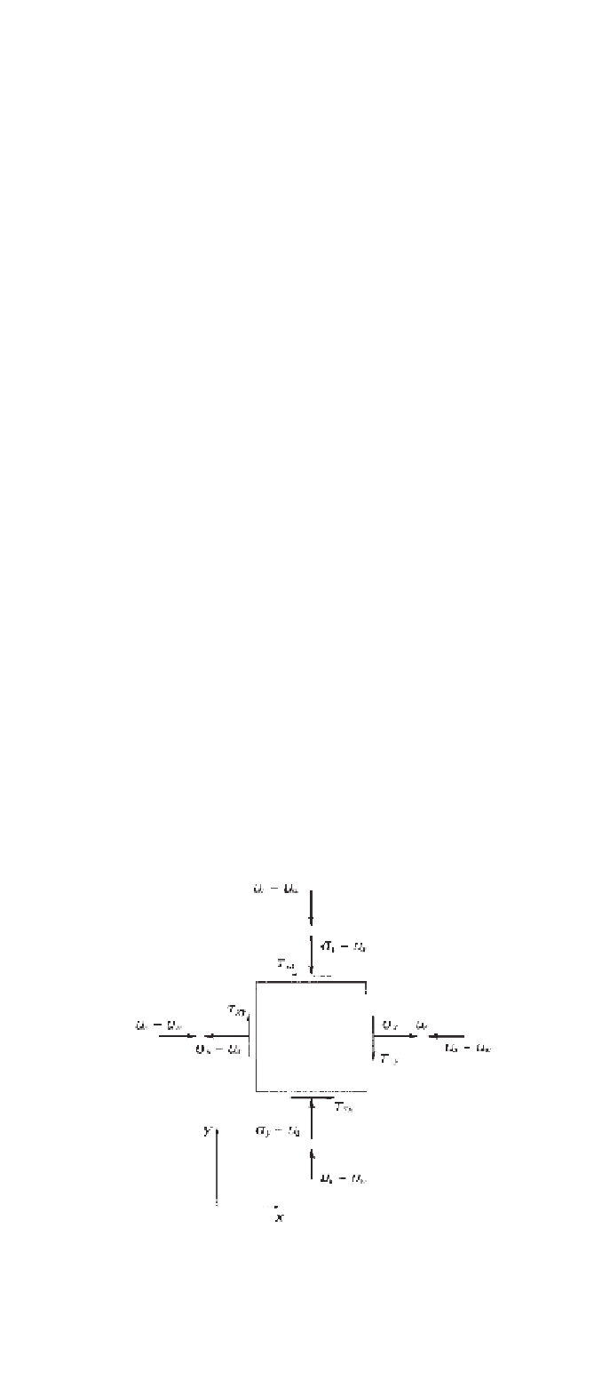
The principal planes are not always the vertical and hor-
izontal planes. A more general case is shown in Fig. 3.21
where shear stresses may be present on the vertical and hor-
izontal planes. The principal stresses and principal planes
can be found graphically using the known stresses on the
vertical and horizontal planes. The vertical net normal stress
σ
y
−
−
u
a
)
,
τ
xy
). A line joining the pole
point and the net major or net minor principal stress point
gives the orientation of the major or minor principal plane
(Fig. 3.22). The major and minor principal planes are at an
angle of
α
and
β
with respect to the horizontal, respectively.
The top and the bottom stress points on the Mohr circle
correspond to the planes on which the maximum and mini-
mum shear stresses occur. The maximum and minimum shear
stress planes are oriented at an angle of 45
◦
from the principal
planes.
u
a
is a compressive stress, and the horizontal net nor-
mal stress
σ
x
−
u
a
is negative because it is in tension. The
matric suction
u
a
−
3.5.2 Stress Invariants
There are three principal stresses on three mutually orthog-
onal principal planes in a three-dimensional analysis. The
three principal stresses are named according to their mag-
nitudes, namely, the net major stress, the net intermediate
stress, and the net minor principal stress. The symbols used
for the net major, net intermediate, and net minor principal
stresses are
σ
1
−
u
w
acts on every plane with equal mag-
nitude. The shear stresses
τ
xy
and
τ
yx
are always equal in
magnitude and opposite in sign.
The extended Mohr circle for the stress state shown in
Fig. 3.21 is presented in Fig. 3.22. The Mohr circle is drawn
on the
τ
-and-
(σ
u
w
axis is determined by the magnitude of the matric suction.
The first step in plotting the Mohr diagram is to plot the
stress points which represent the stresses corresponding to
−
u
a
)
plane. Its position along the
u
a
−
u
a
, respectively. A
corresponding Mohr circle is shown in Fig. 3.23. The matric
suction acts equally on all three principal planes.
The principal stresses at a point can be visualized as
the characterization of the physical state of stress. These
principal stresses are independent of the selected coordi-
nate system. The independent properties of principal stresses
are expressed in terms of constants called stress invariants.
There are three stress invariants that can be derived from
each of the two independent stress tensors for an unsatu-
rated soil. The first stress invariants of the first and second
stress tensors, respectively, are
u
a
,
σ
2
−
u
a
, and
σ
3
−
I
11
=
σ
1
+
σ
2
+
σ
3
−
3
u
a
(3.50)
and
I
12
=
3
(u
a
−
u
w
)
(3.51)
where:
I
11
=
first stress invariant of the first tensor and
I
12
=
first stress invariant of the second tensor.
Figure 3.21
Stress state at point in unsaturated soil.


Search WWH ::

Custom Search