Hardware Reference
In-Depth Information
V
DD
3
TXD
dominant
detect
V
DD
Thermal
shutdown
1
TxD
Driver
control
7
Power-
on reset
CANH
Slope
control
R
S
V
DD
8
RxD
Receiver
4
GND
6
CANL
Reference
voltage
V
REF
5
2
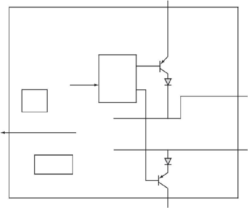
Figure 13.43
■
The block diagram of Microchip MCP2551
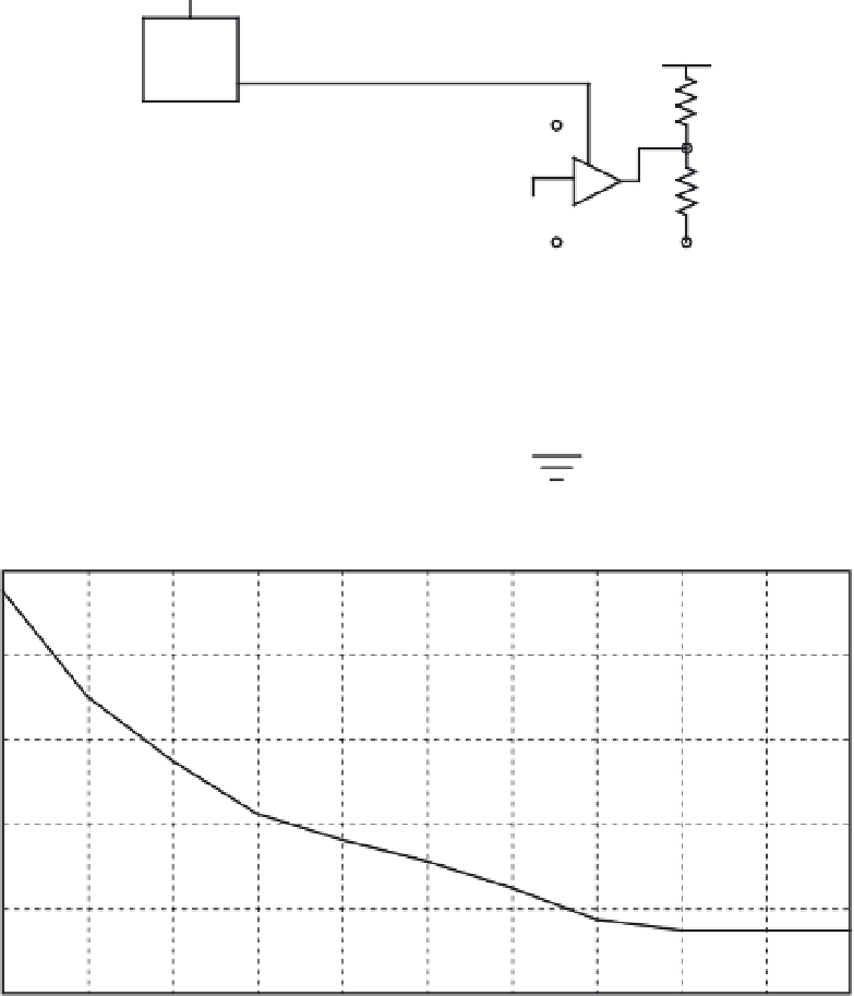
25
20
15
10
5
0
10
20
30
40
49
60
70
80
90
100
110
Resistance (k
Ω
)
Figure 13.44
■
Slew rate versus slope control resistance value


Search WWH ::

Custom Search