Hardware Reference
In-Depth Information
CANCLK
Tq clk
Oscillator clock
E-clock
RxCAN
MUX
Prescaler
Receive/
transmit
engine
TxCAN
Control
and
status
Message
filtering
and
buffering
Tx int. req.
Configuration
registers
Rx int. req.
Err. int. req.
Wake-up int. req.
Wake-
up
Low-pass
filter
Figure 13.13
■
MSCAN12 block diagram
transceiver chip such as the MCP2551 (from Microchip) or the PCA82C250 (from Philips) to
interface with the CAN bus. In addition to providing large driving current, a CAN transceiver
chip has current protection against defected CAN or defected nodes. A typical CAN system
that includes one or more HCS12 devices is shown in Figure 13.14.
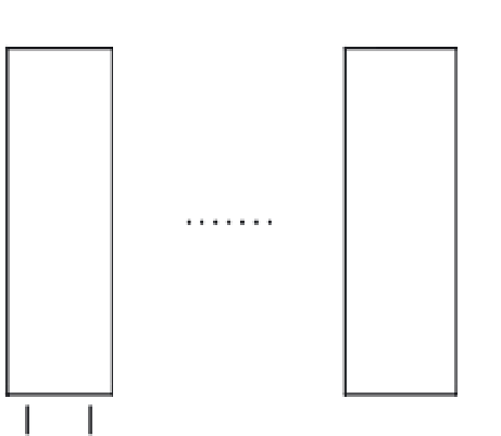
CAN node 1
CAN node 2
CAN node
n
HCS12
CAN controller
(MSCAN12)
RxCAN
TxCAN
Transceiver
CAN_H
CAN_L
CAN Bus
Figure 13.14
■
A typical CAN system


Search WWH ::

Custom Search