Hardware Reference
In-Depth Information
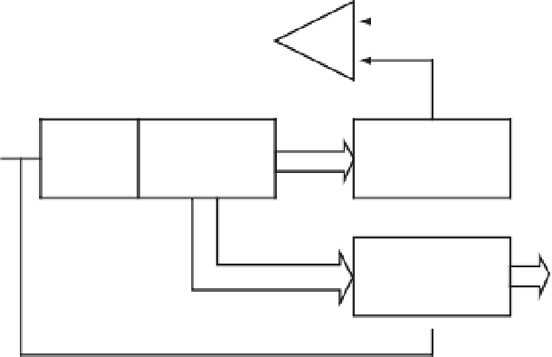
Analog
comparator
+
V
IN
(analog input)
-
V
RH
Successive-
approximation
register (SAR)
Control
logic
Digital-to-analog
converter
Clock
V
RL
Output
latch
Digital
code
Figure 12.4
■
Block diagram of a successive-approximation A/D converter
Start
SAR[n
- 1, . . . , 0]
←
0
i
←
n - 1
SAR[i]
←
1
Convert the value in
SAR to a voltage
←
i - 1
Is the
converted voltage
greater than
the input?
Yes
SAR[i]
←
0
No
No
i = 0?
Yes
Stop
Figure 12.5
■
Successive-approximation A/D conversion method


Search WWH ::

Custom Search