Hardware Reference
In-Depth Information
The circuit connection of a 24LC08B and the HCS12 MCU is similar to that in Figure
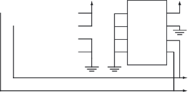
11.34. The diagram of a system with one DS1631A and one 24LC08B and the HCS12 MCU is
shown in Figure 11.40.
5 V
5 V
HCS12
DS1631A
24LC08B
2.2 k
2.2 k
Ω
Ω
5 V
5 V
V
DD
V
DD
SDA
SDA
A0
SCL
SCL
WP
A0
A1
INT0
T
OUT
A2
SCL
A1
SDA
V
SS
GND
A2
SCL
SDA
Figure 11.40
■
Circuit connection of the HCS12MCU, 24LC08B, and DA1631A
Example 11.15
▼
Write a function to read a byte from the 24LC08B. Pass the control byte and address in ac-
cumulators A and B to this subroutine. Return the data byte and error code in A and B, respec-
tively. This function should check the error that the EEPROM did not acknowledge (implies
that 24LC08B may have failed).
Solution:
The following assembly subroutine implements the procedure for random read
described earlier:
EErandomRead
jsr
sendSlaveID
; send out 24LC08B ID and block address
brclr
IBSR,RXAK,ranRdok0
; does EEPROM acknowledge?
ldab
#$FF
; return
2
1, if EEPROM does not ackowledge
rts
ranRdok0
stab
IBDR
; send out EEPROM memory address
brclr
IBSR,IBIF,*
; wait until the address is shifted out
movb
#IBIF,IBSR
; clear IBIF flag
brclr
IBSR,RXAK,ranRdok1
; does EEPROM acknowledge?
ldab
#$FF
; return
2
1, if EEPROM does not ackowledge
rts
ranRdok1
bset
IBCR,RSTA
; gener
ate
restart condition
oraa
#$01
; set R/W bit for read
staa
IBDR
; resend the device ID


Search WWH ::

Custom Search